Current Transformer [CT] is used to obtain replica of primary current for use in metering or relaying applications. Though vast majority of applications only require one CT per phase, there could be situations where one or more feeders from the same phase need to be monitored. Examples are:
- Single meter need to combine load of two branch circuits.
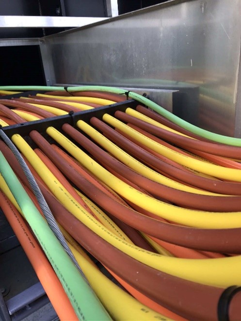
- Due to large number of parallel cables, a single CT to encompass all cables may not be practical and hence parallel CT need to be used.
Read: How to select taps for multi ratio CT?
When it is desired to parallel multiple CT secondary, the following should be considered:
- CT’s to be paralleled should have the same CT ratio and preferably same manufacturer and part number.
- All CT’s that are paralleled should be installed using same polarity direction.
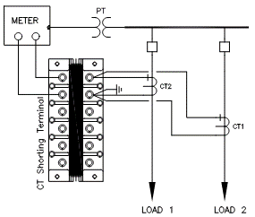
- Secondary circuit of each CT need to be paralleled at or near the meter and not at the CT.
- Use one common return for the CT return circuit.
- Use one common ground for CT secondary circuit.
- Voltage signal needs to be derived such that even if one feeder is turned OFF, the meter can record power data.
- Meter or device connected need to be capable of carrying the sum of current from all the CT’s.
- For ease of maintenance and troubleshooting it is good to have CT terminal (shorting) block. CT terminal block will help terminate multiple wires and also aid in testing and troubleshooting.
- It is recommended to keep the CT lead length comparable between parallel CTs to keep the wire burden similar. If one CT is further away, then secondary lead wire diameter for that CT may have to be increased to keep the burden similar and prevent CT saturation.
- Accuracy will not be degraded by paralleling if the combined current does not exceed the rated current of the meter.
- It is recommended to clearly label or color code each wire to aid troubleshooting.
Read: Neutral current transformer applied with electronic trip units
Sizing Parallel Current Transformer
When CTs are installed in multiple branch circuits, CT size must be equal to or greater than the sum of the maximum currents expected out of each branch circuit.
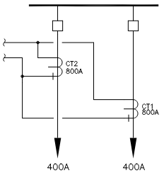
Example 1: If there are two branches and maximum load on each circuit is 400A then the CT primary rating needs to be atleast 400A+400A= 800A. Assuming the meter is rated for 5A secondary, each 800: 5 CT would produce 2.5A giving a total full load secondary current of 5A to meter.
Read: Potential transformer accuracy class
If the CT was incorrectly sized at 400:5 per the full load (400A) of each branch and not the sum of each branch current, then the meter input current would be 5A+5A=10A thus overloading or possibly damaging the meter with 5A rated input.
Read: Open circuit CT characteristics
Example 2: If there are three branches with load current of 200A, 300A and 500A, then each CT that need to be paralleled need to be 200A+300A+500A= 1000A primary rated.
Read: Adjusting current transformer ratio
Effective CT Ratio for Parallel Current Transformers
Two similar current transformers with their secondary in parallel will have an overall reduced CT ratio when compared to a single CT. Let’s evaluate this using an example.
Consider 150:5 CT with 3,000A of primary current and a connected burden of 1Ω. This CT will have a transformation ratio [CTR] of 150/5=30. For the given primary current, CT will produce 100A of secondary current. Now consider two such 150:5 CT in parallel. For the given primary current, secondary current from both CT will add to 200A. Effective CTR can be calculated to be 3000A/200A= 15. Compare this with CTR before paralleling.
Read: CT open circuit protector
Accuracy for Parallel Current Transformers
Accuracy improvement when CT’s are paralleled arise from intentionally using a larger and more accurate CT compared to base case of using only one CT. Just paralleling two similar CTs will not result in any improvement of accuracy and in fact might reduce the accuracy. Let’s evaluate this using an example.
Consider 150:5 CT with 3,000A of primary current and a connected burden of 1Ω. Secondary voltage across burden will be 100V. When two such CTs are put in parallel, the effective secondary current is 100A+100A=200A. Voltage across burden (which is also excitation voltage) is 200V. Excitation voltage has doubled in this case and lead to less accurate CT. Now let’s see how accuracy can be improved in next example.
Read: Zero sequence current transformer
Consider 150:5 CT with 3,000A of primary current and a connected burden of 1Ω. Secondary voltage across burden will be 100V. Now, consider replacing 150:5 CT with two 300:5 CT connected in parallel with same 3,000A of primary current. Each CT will produce 3000/60=50A current for a total of 100A through burden. Burden voltage will be 1Ω*100A=100V. Notice that this is the same voltage as single 150:5 CT but now we have larger 300:5 CT with (hopefully) higher accuracy class. This contrasts with series connection of CT where the very connection between two CT in series lowers the excitation voltage across CT and improve accuracy.
Read: Three phase current metering using two current transformers