Open circuit condition in a current transformer (CT) can result in dangerous over voltage condition at the secondary terminals of the CT. An open circuit CT especially of high ratio and carrying high currents can produce secondary open circuit voltage in the range of few kilo volts. This voltage is usually sufficient to sustain steady state arcing between CT shorting blocks and is a potential fire risk.
A CT could become open circuited due to wiring error at the time of installation or subsequently due to loose crimping, accidental disconnection or sabotage.
To understand why an open circuited CT creates dangerously high voltage we need to understand the CT equivalent circuit. A CT can be represented using the figure below. In this figure ZE is magnetizing impedance, ZS is the lead impedance and ZB is burden (load) impedance.
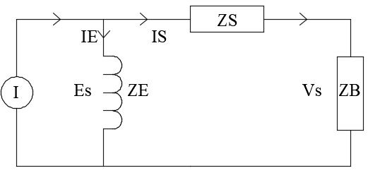
The secondary ratio current flows through the interconnect wiring impedance ZS and the connected load (burden) ZB. A small portion of the current also flows through the CT magnetizing impedance ZE. Under normal circumstances, this magnetizing impedance is very high (in the order of hundreds of kilo ohms) and only a negligible current flow in this circuit.
How does an open circuit CT produce extremely high voltage spikes?
When a CT which is carrying primary current becomes open circuited on the secondary side, the ratio current has nowhere to flow but through the high impedance of the magnetizing reactance ZE. This creates a large voltage drop ES across the impedance ZE in the figure above which drives CT in to saturation. A Saturated CT has lower magnetizing impedance ZE than non-saturated CT and hence the excitation current (IE) increases disproportionally. For high turns ratio CT with secondary circuit open, a small primary current is usually sufficient to saturate the core.
This means that under open circuit conditions, the CT core will be operating under saturation. Under saturation, the rate of change of flux in the CT core is almost zero (it is already carrying the maximum flux due to low magnetizing impedance). However, in the short interval in each half cycle current passes through zero and magnetizing flux is rapidly changed from saturation in one direction to saturation in another direction. During these transition period reactance increases to very high values and exciting current is switched rapidly from positive to negative direction. It is this rapid change of flux during the short interval that is responsible for high open circuit crest voltage. The voltage appears as similarly shaped brief, but extremely high crest (peak) voltage spikes.
Note: When a CT is open circuited, voltage measurement using an RMS volt meter may not show the true voltage and may not appear to be dangerous. It is not the RMS voltage that is high during CT open circuit, but the peak or crest voltage that is very high.
Read: Current transformer saturation
Factors influencing CT open circuit voltage magnitude:
CT turns ratio. Higher the turns ratio, larger the voltage spike.
Material and construction of the CT’s magnetic core.
Primary current level. CT with very high turns ratio with even small primary current can result in high secondary voltage.
Primary voltage- larger the primary voltage the larger the secondary open circuit voltage. This is not a linear relationship and only comes in to play when the CT secondary is open.
Higher the operating frequency, larger the voltage spike.
Open circuit CT symptoms and characteristics:
Arcing across CT shorting blocks or wherever the CT leads are opened.
CT damage due to dielectric damage if the leads are open at the CT itself.
CT starts to make significant audible noise.
CT core temperature may not increase when the CT is open circuited.
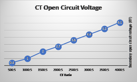
Approximate CT secondary open circuit voltages based on published data based on various measurement data is provided below. The CT’s are carrying the rated primary current. This is for a window type multi ratio CT with maximum tap of 4000:5.
IEEE C57.13 2008 -IEEE Standard Requirements for Instrument Transformers section 6.7 ‘Secondary winding induced voltages’ state that:
“Current transformers should never be operated with secondary circuit open because hazardous crest voltages may result. Transformers conforming to this standard shall be capable of operating under emergency conditions for 1 min with rated primary current times the rating factor with secondary circuit open if the open-circuit voltage does not exceed 3,500V crest.”
“When the open circuit voltage exceeds 3,500V peak, the secondary winding terminals should be provided with voltage limiting devices (varistors or spark gaps)”.
If protection against Current transformer (CT) open circuit protection is desired then varistors, spark gaps or other voltage clamping devices can be used. These CT open circuit protector devices [OCP] are non-linear in their characteristics. Under normal operating conditions the device will be an open circuit. When the voltage across the device is greater than the threshold voltage, the device starts conducting thereby reducing the open circuit voltage. These components (varistors, spark gaps etc.) are sacrificial devices and after multiple conduction cycles it may have to be replaced. OCP on the other hand does not have to be replaced as it is rated to continuously carry CT secondary current.
Click here for article on spark gaps.
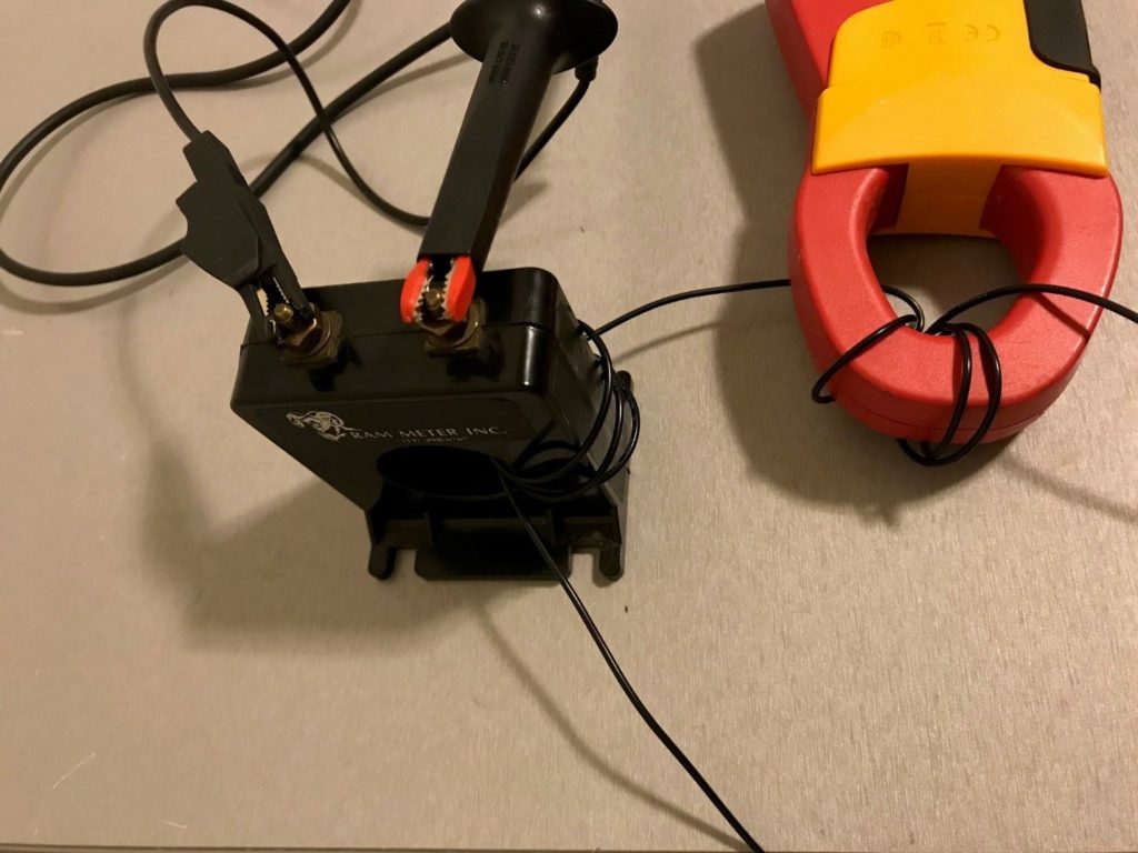
Current Transformer Open Circuit Test and Waveform
In this test a 50:5 CT is open circuited while carrying rated primary current. Secondary open circuit voltage is measured for maximum loading conditions. Secondary open circuit voltage waveform is captured using an oscilloscope showing the crest voltage. The experiment also shows why a rms volt meter will not be able to show the true extent of dangerous over voltage condition when CT is open circuited. The high crest / peak voltage can only be measured with an oscilloscope or a peak reading multimeter.
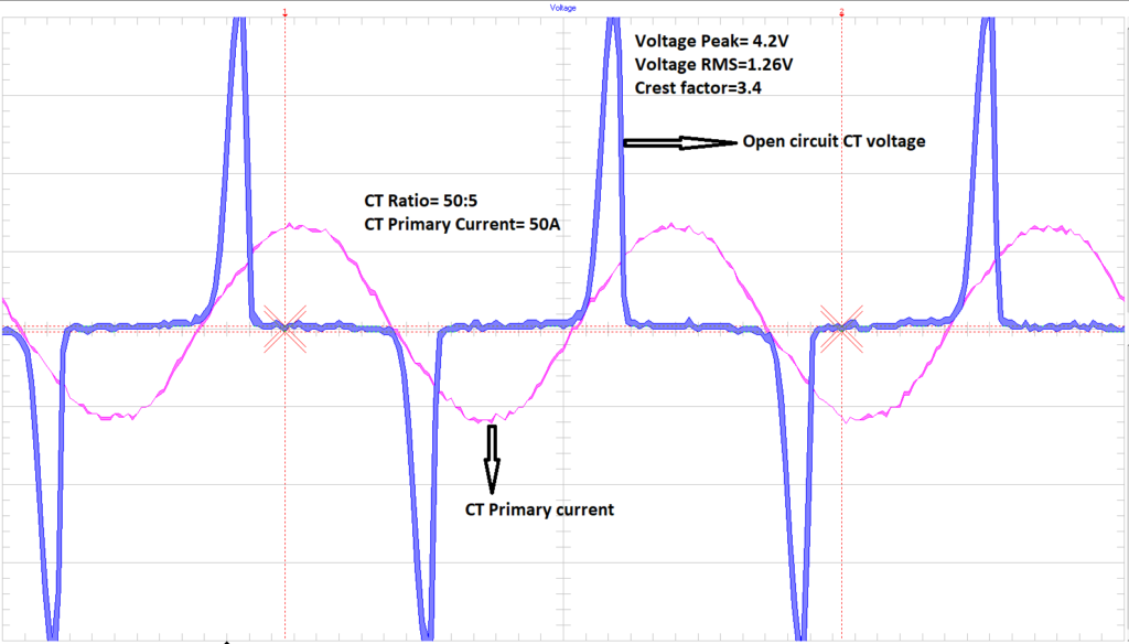
Note that the open circuit voltage appears when the current waveform changes polarity from positive half cycle to negative half cycle.
From the figure above, we can see that the peak value of the open circuit voltage is 4.2V while the rms voltage is only 1.26V. That is peak is more than 3.3 times the RMS. In real world applications with large ratio CT, measurement of open circuit voltage using an RMS voltage may not indicate the true extent of the dangerous voltage present, a peak reading multimeter will be needed. Even with a peak reading multimeter another important consideration is that CT produces open circuit voltage in excess of 1,000V and ordinarily multimeter leads which are only rated for 600V or 1,000V will not be suitable for measurement.