Spark Gap is a generic term for ‘gas tubes’ which consists of a sealed enclosure that uses metal electrodes and a mixture of noble gases (neon, argon etc). Historically spark gaps were used in many applications such as spark gap radio transmitters, electrostatic machines etc. In present day, spark gaps are used to divert or shunt transient energy away from sensitive electronic circuits. When a high voltage transient is applied across the terminals of the spark gap, the gap breaks down electrically thereby diverting the energy to ground and protecting the equipment it is connected to.
Larger version and variations of spark gaps were used in power transmission and distribution. These are largely replaced by Metal Oxide Varistor (MOV) and other modern technologies. Small spark gaps are used in telephone switchboards, printed circuit boards etc to a limited extent.
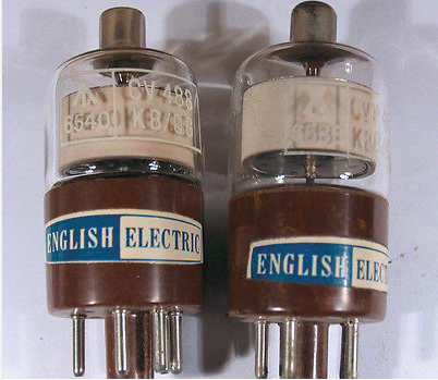
Spark Gap
Principle advantage of Spark Gap is that this device has one of the lowest shunt capacitance of all non-linear transient mitigating devices. Typical values are between 0.5pf to 2pf. In applications with high frequency signals, low shut capacitance is advantageous since high capacitance will lead to degradation of signal quality.
Modern Spark Gaps can conduct current 5kA-20kA without appreciable damage to the spark gap electrodes. The device is not polarity sensitive in the sense that it does not matter if either electrodes are connected to positive or negative or phase and neutral of the supply line.
V-I Characteristics of Spark Gap
The VI characteristics of spark gap can be summarized as shown in the figure below.
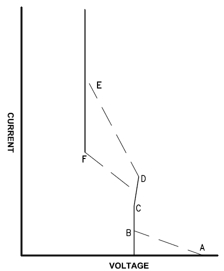
Spark Gap VI Characteristics
The various regions can be identified as follows:
Region A-B: At point A the spark gap starts the transition from insulating to a conducting state. The voltage at A is called the DC firing voltage of the gap. Between points A and B the device exhibits negative resistance.
Region B-C: This is known as the normal glow region. In this region the device maintains a constant voltage across the terminals for a range of current. This property is used in voltage regulators using vacuum tubes. The cathode starts to glow in this region.
Region C-D: This region is known as the abnormal glow region. The dV/dI is positive in this region and the device exhibits positive resistance unlike region A-B. The glow covers the entire cathode region in this phase. The light emitted in the normal glow or the abnormal glow region contains the spectral lines that are characteristic of the gas that is used in the spark gap. For argon gas the color is blue-violet, for neon gas it is orange-red.
Point E: At point E the current has sufficiently increased in magnitude enters what is known as the arc regime. In this region the potential across the spark gap is essentially constant at about 20V (independent of current). By using different gases and different pressures this voltage can be changed. In overvoltage applications, it is desired to operate the spark gap in the arc regime since the voltage is clamped to a relatively small value.
During arc regime, the metal atoms at the cathode electrodes can become dislodged due to positive ion bombardment. This bombardment of the cathode can cause a phenomenon known as ‘Sputtering’. The black deposits that we can see on the neon lamps are the result of this electrode sputtering by high energy ion impact on the electrode. This process can lead to degradation and wastage of the electrode material that would result in increase in spark gap length and ultimately making the device not effective at transient voltage mitigation. By careful engineering the electrode material can be made to be sufficiently robust to prevent rapid sputtering. In any case the spark gap can be considered a sacrificial device in the sense that after taking sufficient current the device will have to be replaced or its effectiveness will keep decreasing.
Point F: When the current reduces to point F the arc stops. This point on the V-I characteristics is known as arc extinguishing current. The value of arc extinguishing current is around 0.1 to 0.5A.
If we observe the V-I characteristic there is hysteresis. The current required to initiate the arc is greater than the current required to sustain the arc.
Spark Gap Failure Modes
Spark Gap when conducting can cause large rise in temperature and can fail leading to the insulating case to crack or even let the atmospheric air to enter the case. Once the atmospheric air enters, the DC firing voltage of the spark gap can increase as much as 20 times making it ineffective for transient voltage mitigation applications.
The metal atoms at the cathode electrodes can become dislodged due to positive ion bombardment during spark gap conduction. This bombardment of the cathode can cause a phenomenon known as ‘Sputtering’ leading to cathode material to ‘blast away’. The electrodes are eroded and consumed during this process which leads to increase in gap length and ultimately making the device not effective.
Follow Current
If the normal voltage or current source can sustain the arc then the spark gap will not return to non-conducting state and can lead to the devise failure due to overheating. This is known as power follow or follow current. Follow current can maintain conduction in either arc or glow regime. Some of the methods to prevent follow current are:
- Use a resistor in series with the spark gap
- Use a varistor in series with the spark gap
- Use a fuse in series with the spark gap
Spark Gap Selection
Spark Gap can be selected by following the below equation.
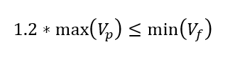
where max(Vp) is the peak magnitude of the voltage during normal operation and min(Vf) is the minimum DC firing voltage of the spark gap. Tolerances should be included for both voltages.
Disadvantages of Spark Gaps
Some of the disadvantages of the spark gap are:
- They could be slow to conduct
- Follow current could result from spark gap continuing to conduct after a transient operation
- The conduction itself can lead to electromagnetic emissions that may interfere with sensitive electronics
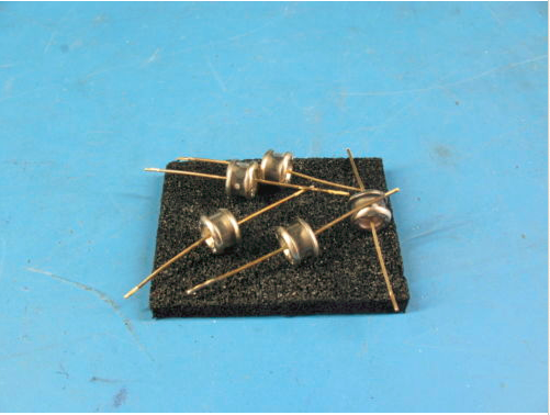
Types of Spark Gaps
- Two electrode spark gap
- Three electrode spark gap
- Coaxial spark gap
Two electrode spark gap as the name signifies has two electrodes. Three electrode devices have one extra electrode in the middle which connects to local ground or earth. This configuration is useful for protecting balanced transmission lines such as telephone lines, computer data communication lines etc. Three electrode spark gap provides both common mode and differential mode protection in a single component. Coaxial spark gap as the name signifies is used in protecting coaxial transmission cables. The low shunt capacitance of the spark gap is very useful property when used in coaxial lines as the signal attenuation is less.