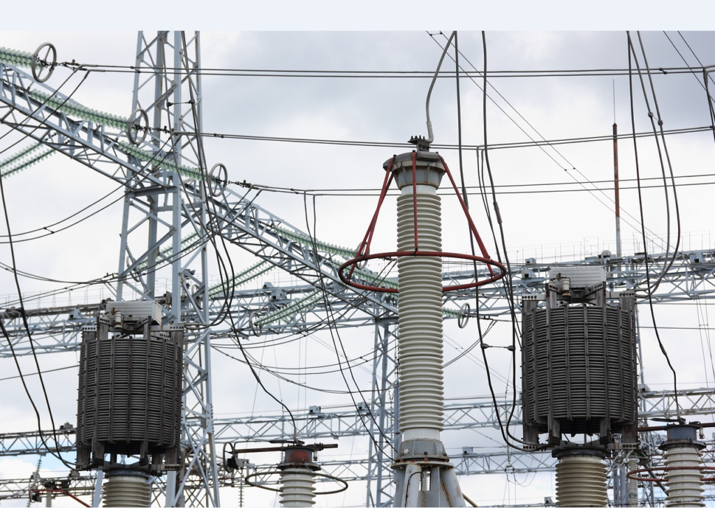
Current Limiting Reactor (CLR) is used to reduce the available short circuit level to a value that matches the rating of the switchgear or to meet other design requirements. Available short circuit current can increase due to additional generation capacity added or due to design and layout of bus tie breakers. Often the switchgear is only rated for a given value of short circuit rating and the additional generation capacity or additional tie breakers can potential create a situation where the available short circuit current is above the rated capacity of the switchgear.
Some of the methods to reduce the available short circuit current are:
- Series Current Limiting Reactors
- Solid State Fault Current Limiters
- Superconducting Fault Current Limiters
In this article we will discuss about Series current limiting reactor.
Different from CLR, current limiting fuses are used to limit the let through current such that the fuse interrupt the short circuit current before quarter cycle of the short circuit current waveform. Note that current limiting fuse doesn’t necessarily reduce the steady state short circuit current. It only limits the short circuit from reaching its actual value after which the fuse will have to be replaced.
What is a series Current Limiting Reactor?
Current Limiting Reactor [CLR] as applied in industrial power system is an inductive component connected in series with the source of power on one side and the load bus on the other side-most common installation method. CLR reduce the available short circuit current by providing additional the impedance in the fault circuit. CLR could also be applied between two separate sections of switchgear, on the feeder sections, as outrush limiting reactors for capacitor banks etc.
The figure below illustrates the common applications of current limiting reactors.
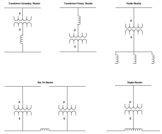
Common connections of Current Limiting Reactor
Transformer secondary reactor is used after the transformer to limit short circuit current on the secondary bus. This is a common application of current limiting reactor. Transformer primary reactor shown above is not very common.
Feeder reactors are used to limit the short circuit current on individual feeders. Installing feeder reactors instead of one large transformer secondary rector is advantageous for the following reason. Installing one secondary reactor creates a larger voltage drop (which depends on system power factor) compared to having individual feeder reactors. The feeder reactors will only have to carry the current of that particular feeder and not the entire substation. Thus, the voltage drop across any given feeder will be much less than the one reactor at the secondary. However, this may not be practical in all situations since the goal usually is to reduce the short circuit current at the transformer secondary bus.
Bus tie reactors are used when two buses are tied together and short circuit limitation is desired.
Duplex reactor: If two single phase reactors are physically arranged such that their magnetic fields are interlinked in an opposing fashion, a duplex reactor is formed. Normal operating current would create flux that would cancel each other and hence no voltage drop would be created. When a short circuit occurs on one side of the bus, the magnetic fields become unbalanced and the reactor behave like a regular current limiting reactor.
Air core current limiting reactors are used almost invariably for current limiting applications, though oil filled reactors are also used sometimes.
Does series Current Limiting Reactor create voltage drop?
The voltage drop across the reactor is a function of the load power factor. The load power factor need to be calculated and if the load has reasonably good power factor (>90%), the voltage drop is usually not a concern. Use the calculator below for calculating the estimated voltage drop as a function of load power factor for a given reactor percentage impedance %Z.
Lets consider two extreme cases. One with ideal unity power factor (Cosθ=1 or θ=0) and another with non-ideal zero power factor (Cosθ=0 or θ=90).
Unity Power Factor Load
When the load has unity power factor (Cosθ=1 or θ=0) meaning the load current is in phase with the system voltage, the reactor voltage drop is at right angles to the sending end voltage. See the phasor diagram below for more details.
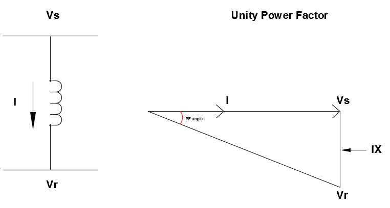
Current Limiting Reactor-Unity Power Factor
As can be observed only a little voltage regulation is created along with a phase angle difference across the reactor. The actual voltage drop across the reactor is IX, directly proportional to current. Only the angle at which it combines with the supply voltage changes with the load power factor.
Zero Power Factor Load
When the load has zero power factor (Cosθ=0 or θ=90) meaning the load current has 90 degree phase angle difference with the system voltage, the reactor voltage drop subtracts (or adds) arithmetically from the receiving end voltage. See the phasor diagram below for more details.
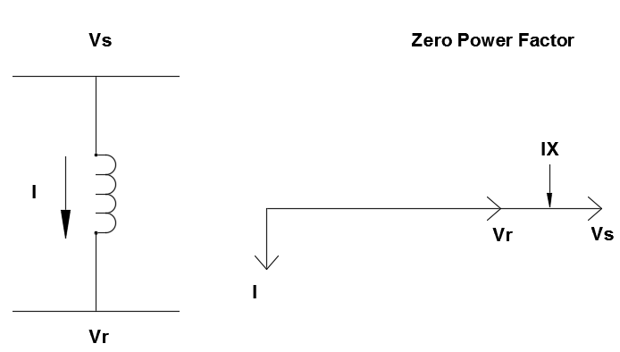
Current Limiting Reactor-Zero Power Factor
By observing the phasors carefully, it can be deduced that for a unity power factor load (θ=0), the voltage drop is minimal compared to the case with poor or zero power factor (θ=90).
Feeder reactors typically will have 3-5% reactance while synchronizing bus reactors sometimes reach values of 7.5-10%. Voltage drop considerations place an upper limit on the reactance of current limiting reactor.
Use smaller reactors on the feeder circuits instead of a large reactor on the main incomer. The voltage drop across one large reactor will be substantially larger than having three smaller feeder reactors. The kW loss would be similar for either designs. This design may not be practical as the intent of the reactor may be to limit the short circuit current on the main bus or there may not be enough physical space to install multiple feeder reactors instead of one main reactor.
Types of Current Limiting Reactor: Air Core Reactor vs Iron Core Reactor
Primarily two types of reactors are used. Air core dry type or Iron core dry or oil filled reactor. For short circuit current limiting applications, air core dry type reactors are most commonly used. Iron core reactors though occupies less physical space can saturate when high magnitude short circuit current flows through them. Saturation reduces the effective impedance making it not an effective candidate for short circuit limiting applications. Air core reactors on the other hand do not suffer from this drawback, though they have other limitations as described below.
Advantages of air core reactor:
- Saturation does not occur when a high fault current flows in air core reactor. Iron core reactors on the other hand will saturate when high fault current flows through the reactor. Saturated reactors will have less impedance and hence will not be able to limit the short circuit current.
- Dry type air core reactors have low losses (high Q) and operate efficiently with virtually no major maintenance required.
- Generally, air core reactors can be installed vertically stacked or side by side. Necessary magnetic clearances recommended by manufacturer need to be followed.
Disadvantages of air core reactor:
- Air core reactor by its nature produces more stray magnetic field compared to an iron core reactor. Iron core reactor confines the magnetic flux within the core, whereas there is nothing in the air core reactor that can confine magnetic flux.
- Due to potential interaction of magnetic flux between reactors of different phases in a three-phase reactor stack, manufacturer suggested clearances will have to be provided. This means the air core reactors will occupy larger physical space.
- Due to potential magnetic flux exposure, additional personnel safety fencing may have to be installed to prevent unnecessary personnel exposure to high magnetic field.
- Equipment and sensitive electronics susceptible to high magnetic field should be kept outside the magnetic field boundary suggested by the manufacturer.
Current Limiting Reactor Specifications
Some of the reactor specifications are listed below. This is not a complete list and there could be other important parameters that need to be considered depending on the application.
- Inductance
- Impedance
- Available Fault Current
- Nominal Frequency
- Continuous Rated Current
- Rated Voltage
- Voltage Drop
- Losses
- Basic Insulation Level
- Dry or Oil Type
- Indoor or Outdoor
- Mounting Arrangement
Each of these are discussed below:
- Inductance, Impedance & Available Fault Current
Selecting the right inductance (impedance) based on the available fault current and required reduction in short circuit current is one of the most important design steps in selecting a CLR. How to select the right inductance for a CLR? Use the calculator at the end of this article to calculate the required inductance.
- Nominal Frequency
The frequency at which reactor is applied. Usually 50/60Hz.
- Continuous Current
The continuous load current that would flow in the circuit.
- Rated Voltage
The rated voltage of the reactor.
- Voltage Drop
The voltage drop across a current limit reactor is a function of the load power factor. If the load power factor is close to unity, then the voltage drop will be negligible. Use the voltage drop calculator above to estimate the % voltage drop for various load power factor.
- Losses
Often a rector can be designed for optimal cost while adhering to relevant standards or be designed to minimize steady state losses in the reactor. Since reactor is a series device, any steady state loss will be present throughout the operating life of the reactor. Aluminum or Copper windings are the obvious choice for winding with Aluminum being light weight with higher resistive losses compared to copper.
- Basic Insulation Level
Insulation strength of reactor. Selected based on voltage class and application requirements.
- Dry or Oil Type
Current limiting reactors used for short circuit current reduction are more than likely to be dry air core type. Oil type could be available from some manufactures.
Oil immersed reactors can be applied in heavily polluted areas. Oil also has higher dielectric strength resulting in overall smaller foot print. Heat transfer capability of oil is higher which can help with the continuous current rating of the reactor.
- Indoor or Outdoor
Whether the reactor is installed indoors or outdoors, the following conditions should be checked:
- Clean and flat surface
- Clean, dry and dust free air
- Free air movement
- No flammable substance
- No metallic parts near reactors that form closed loop.
- Required clearances between various metal parts and reactor be maintained per manufacturer recommendations.
- Look for any buried structural steel that might create a closed loop.
- Mounting
Air core reactors can be mounted vertically stacked following manufacturer recommendations or placed in a horizontal plane.
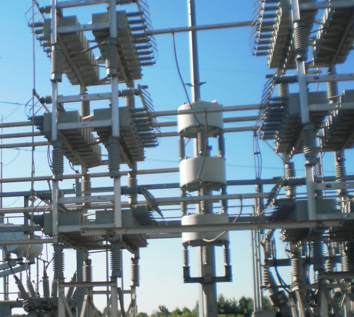
Vertically stacked air core reactor
Other considerations:
- Transient Recovery Voltage (TRV)
It is recommended to evaluate if the presence of current limiting reactor create any large Transient Recovery Voltage (TRV) when a fault is cleared. It may be required to do a transient analysis to figure this out. If TRV in excess of reactor/breaker capacity is found then appropriate surge arrestors need to be provided. Following points are noted:
In general, it can be seen that application of CLR leads to reduced peak of TRV which is good.
In general, it is seen that application of CLR leads to increase in RRRV (Rate of rise of Recovery Voltage) and may affect breaker opening. Transient studies can help determine if this is a problem for the specific application.
- Magnetic Clearances
Due to the nature of air core reactors, the magnetic field is not confined to the reactor. In fact, all of the magnetic field will be in the air surrounding the air core reactor. This is in contrast with iron core reactor where most of the magnetic field is confined to the iron core and very little stray magnetic fields exist. The magnetic field created by the air core reactors could interact with closed electrical loops or structures and create heating effects. These include metallic parts of the substation close by the reactor, steel reinforcing in concrete, substation structural steel. Manufacturers recommend the suggested magnetic clearances and this must be followed strictly. Some manufacturers also offer non-magnetic extension brackets to maintain the necessary magnetic clearances below the reactor. Usually the manufacturer will be able to perform magnetic distribution analysis for the reactor with the existing substation metallic structures and come out with recommendations. Care should be taken while connecting ground wires to the reactor to not form a closed loop.
- Voltage Regulation
Negligible at normal power factor. Poor load power factor can lead to voltage regulation issues and needs to be factored in to during the design stage.
- Reactor Losses
Negligible since the reactor resistance is usually very small to create large resistive losses. The resistance of the reactor needs to be kept in control for achieving this and most reactor manufactures do a good job at it.
- Transient Stability
When current limiting reactors are applied at large power transmission interconnection networks, evaluation to determine transient stability may be carried out.
- Reactor Taps
Reactor taps may be requested if variable inductance is desired. Having variable taps is especially useful if the short circuit currents could change in the future or if the reactor is part of a harmonic filter application where fine adjustment of inductance value in the field is required for tuning purposes.
- Corona Rings
If the application voltage warrants use of corona rings then that may be requested from the manufacturer.
- Dynamic force calculations
Depending on the short circuit current, it is recommended sometimes to have the manufacturer perform a dynamic force calculation on the structural supports to ensure the integrity of the core is not compromised during a short circuit event.
- Seismic analysis
Air core reactors are top heavy components and depending on the critical nature of the substation it may be useful to analyze the seismic vulnerability of the structural design. This is especially important if the substation is in an earthquake prone area. If deficiencies are found, additional structural supports or vibration dampers can be added.
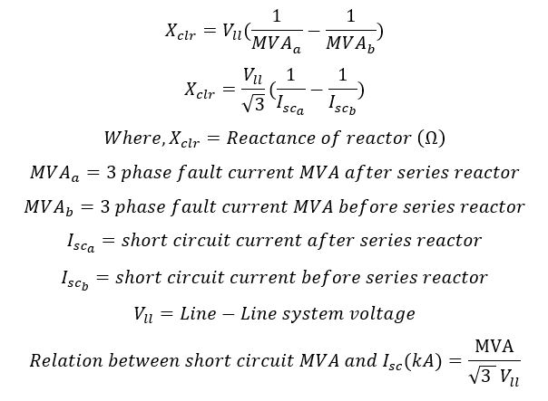
Current Limiting Reactor Sizing
Important formulas relevant to current limiting reactor sizing are provided below:
Current Limiting Reactor Sizing Calculator
Use the sizing calculator below if the short circuit MVA or the actual short circuit value is known.
Use the calculator below if the value of inductance need to be calculated for a given % reactor impedance.
Other Applications of Air Core Reactors
- Neutral grounding reactor
- Smoothing reactor
- Harmonic filter reactor
- Shunt reactors
- Duplex reactor
- Bus tie reactor
- Damping reactors
- Discharge reactors
- Arc furnace series reactors
- Power flow control reactors
- Motor starting reactors