A series tuned harmonic filter is a combination of inductor and capacitor designed to trap a certain harmonic. These filters are applied in parallel with the power system and is often called shunt passive filters. For most harmonic filters in power systems, filters are tuned to 4.2 or 4.7 for trapping 5th order harmonics. For capturing 7th order, harmonics filters can be tuned to 6.7. These filters are often called ‘detuned’ filters since they are not tuned to the exact harmonic order. Exact tuning of filter to 5th or 7th is usually not done due to additional cost and engineering required to size those filters. Exact tuning if desired can be done using the calculator below. Device tolerance and component degradation could result in shifting of tuning point over time and has to be considered during the design process.
Harmonic filter design involves initially selecting the size of reactive compensation (kVar) desired. This could be based on the need for power factor correction or based on the size of capacitors available commercially. Note that if capacitor kVar is made minimum then the size of harmonic filter reactor increases. So there has to be compromise made between inductor and capacitor selection in shunt passive filter design.
The harmonic filter calculator below can be used to calculate the filter parameters needed to tune to a particular frequency.
Harmonic Filter Calculation
The following are the basic steps involved in design of single tuned or detuned power system harmonic filter calculation. These passive power filters are used in control of harmonics in industrial and commercial power systems.
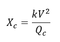
Step1: Determine the capacitor size Qc (Mvar) needed to meet the reactive power requirement of harmonic source.
Step2: Determine capacitor’s reactance.
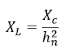
Step3: If hn is the harmonic order that is desired to be trapped, calculate the value of inductive reactance needed using the equation below.
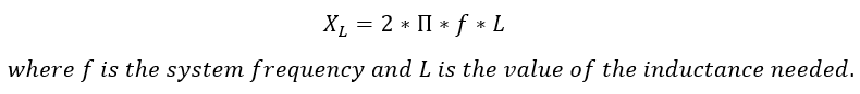
Value of harmonic filter reactor can be calculated using
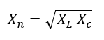
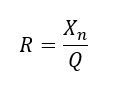
Step4: Find the characteristic reactance Xn and the resistance of reactor.
If Q is the filter’s desired quality factor (typically between 30-100), then the resistance can be calculated as:
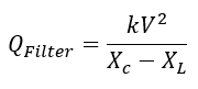
Step5: Effective filter size (Mvar) can be calculated using
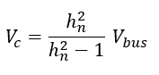
Step6: Voltage appearing across capacitor is
Additional Reading:
Star and Delta Connection of Capacitors , Capacitance Calculator, Resonance Calculator, Delta Wye Conversion Calculator, KVAR to Amps Calculation