For sizing the overcurrent protection, it is often necessary to calculate the full load current of a capacitor bank. The interesting part about calculating power factor capacitor full load current is that there are multiple parameters and variables that need to be considered. Many of these parameters may not be known at the time and engineering estimates has to be made. Some of the variable that determine the capacitor bank current are:
- Capacitor tolerance
- Voltage tolerance
- Harmonics in the system
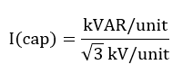
KVAR TO AMPS CALCULATOR – THREE PHASE
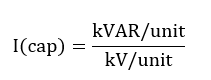
KVAR TO AMPS CALCULATOR – SINGLE PHASE
For example 25 kVAR capacitor current can be calculated to be 4A for a 7,200V single phase system with 10% capacitor tolerance and 5% voltage tolerance.
Capacitor continuous current
The continuous fundamental current of a single phase capacitor is given by:
The continuous fundamental current of a three-phase capacitor is given by:
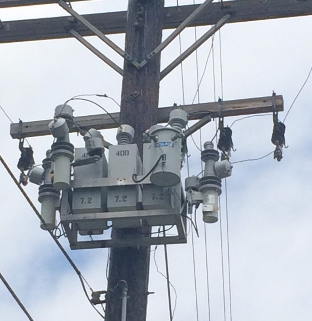
Medium Voltage Capacitor Bank 1200kVAR. Each unit is rated for 400kVAR at 7.2kV
For the system shown in the picture above, capacitors are rated at 400kVAR at 7.2kV. Individual capacitors are connected line-neutral. The System line-line voltage is 12,470V. The net rating of the bank is 400*3=1,200kVAR. To calculate the full load current, enter 1,200kVAR as rating and voltage as 12,470V in the three phase calculator above. Apply additional tolerances as required.
Other factors affecting capacitor continuous current
Even though capacitor current can be calculated using the equations above, it will not be very accurate due to the various other factors affecting the current equation. Each of these are discussed below:
Capacitor Tolerance
IEEE STD 18-2012 , which is the standard for shunt power capacitors allow capacitor tolerance between 0-10%. This tolerance could be +15% according to IEC standard. This means a capacitor with 100kVAR name plate data could deliver anywhere from 100-115kVAR of reactive power and consequently draw larger current.
It is usually possible to get the manufacturing tolerance from the manufacturer or measure the capacitance and determine the tolerance.
Voltage Tolerance
Capacitors are designed to be operated continuously at or below their rated voltage. The power grid voltage is rarely near the nominal value and +/- 5% variation is considered normal. Some locations and facilities might experience even +/-10% tolerance.
Voltage tolerance is established by various national standards such as ANSI C84.1.
Capacitors that follow IEEE 18 standard is capable of operating under the following contingency voltage conditions:
- 110% of rated rms voltage
- 120% of rated peak voltage
The reactive power output of capacitor varies with system voltage based on the following equation:
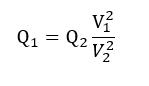
Where Q1 is the reactive power with voltage V1 and Q2 is the reactive power with voltage V2.
Even though the capacitor is capable of operating at 10% overvoltage, it will also draw corresponding higher current which needs to be accounted for in current calculation.
Frequency Tolerance
Frequency variation will affect the reactive power flow from the capacitor. However, in modem power grids frequency variation is negligible and hence can be ignored for capacitor current calculation.
The equation for calculating the variation of reactive power with variation in supply frequency is given by:
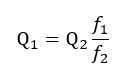
Where Q1 is the reactive power with frequency f1 and Q2 is the reactive power with frequency f2.
Harmonics
When capacitors are placed in power system for power factor correction, it will change the behavior of the system. The capacitor is a low impedance path for harmonic currents. The harmonic voltage present in the system (due to presence of nonlinear loads) will create additional harmonic current flow in the capacitors. This current can cause additional heating and ultimately lead to failure of capacitor if not properly engineered.
To account for the presence of inevitable harmonic currents, voltage tolerance and manufacturing tolerance IEEE STD 18 states that capacitors shall be capable of operating at 135% of nominal rms current based on rated kvar and rated voltage.
When calculating the capacitor current it is recommended to include the 135% rating so that over current protective devices can be sized correctly.
Selection of Capacitor Bank cables and over current devices
As discussed before, the following points must be noted while selecting the cable and over current protective device for capacitor banks:
- Due to capacitor manufacturing tolerances, the capacitance can vary between 0-10% [IEEE] or 0-15% [IEC] of the name plate value.
- The voltage at which the capacitors are applied can vary +5% or even up to +10%. Voltage less than nominal is not a concern for as the lower voltage will result in lower capacitor current.
- Harmonics can create additional current flow in the capacitors any where from +20% to +35% of the rated current.
Considering all of the factors above, the cables and circuit breaker, fuses must be sized.
As an example, if we consider 15% capacitor tolerance, 10% voltage tolerance and 20% additional current due to harmonics then the fundamental capacitor full load current has to be multiplied by 1.15*1.10*1.20=1.518.
Typical values for sizing cables and circuit breakers vary between 1.3-1.5 times the nominal full load current of capacitor bank.
Additional reading:
AC voltage drop and system power factor
How to measure reactive power?
How to calculate reactive power of transformer?