When measuring VFD input current and output current some people become mystified with the current values read on the input side vs the output side. Often times, the output current will be higher than the input current!!. This goes against the conventional knowledge that since the efficiency of the VFD is less than 100%, the output current should be less than the input current.
This article explains the situations surrounding which you can expect to see higher current on the output side of the VFD compared to input side.
There are couple of basics that we need to understand before proceeding:
-
Motors operate at a lagging power factor (PF). This means motor consume reactive power (vars). When the motor is connected to electric grid, the grid supplies the motor with necessary reactive power to operate. This reactive power is used to generate rotating magnetic field inside the stator of the motor and performs no useful work (watts).
-
When a drive (VFD) is installed, it essentially separates the power system in to three separate areas:
-
AC Input side-AC to DC Conversion
-
DC Capacitor Energy Storage
-
Inverter Output side-DC to AC Conversion
-
-
When the motor is connected to VFD (to the inverter output side), the motor is essentially isolated from the electric grid. This means the necessary reactive power to operate the motor must come from the drive itself.
-
The reactive power needed to magnetize the motor windings typically does not vary with speed and is relatively constant value.
-
The real power required to run the motor (torque producing current) however varies with speed. Lower the torque, lower the current will be.
-
It is the total power in to the drive that must be compared to the power output of the drive (minus the power lost in the drive operation). Comparing current between input and output is not a correct comparison.
Current components in a VFD
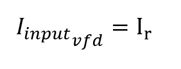
VFD Input Current:
The input current from the electric grid to VFD has one component:
-
The real current that produces torque or useful work (watts)
Input current of the VFD will be the real current that produces useful work or torque.
VFD Output Current:
The output current from the VFD to the motor has two components:
-
The real current that produces torque or useful work (watts)
-
The reactive current that produces magnetic field in motor (vars)
The total output current (Ioutputvfd) from the drive will be the square root of the sum of squares of both the real current (Ir) and reactive current (Iq).
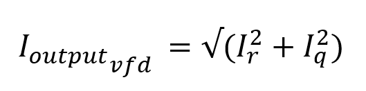
The real current (Ir) is supplied by the electric grid and the reactive current (Iq) is supplied by the DC bus capacitor inside the VFD-See figure. It can be seen from the equations above that the output current of the VFD can be larger than the input current. For smaller size drives and motors the difference in current magnitude may not be noticeable, however for larger drives it will be more pronounced.
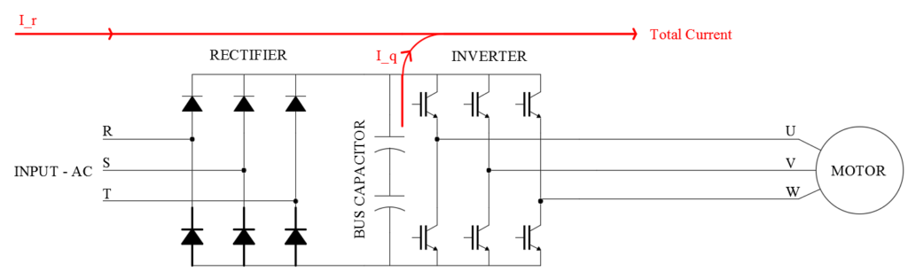
Flow of real and reactive current inside a VFD. I_r is real current and I_q is reactive current.
For the geeks, we can calculate output current from VFD to a reasonable accuracy if we know the motor power factor and the load torque or KW.
Note about measuring VFD output current
It should be kept in mind that the output current from a VFD is very noisy. You could get different readings depending on the type of meter you are using to measure. A meter with a ‘VFD mode’ or “Low pass filter mode’ will give more accurate results.
The best place to measure the VFD output current is the drive display itself. The drive electronics will be able to electronically process the noisy output current waveform and discern the magnitude of the desired current frequency component.
How about measuring VFD input current?
VFD input current for traditional 6-pulse VFD can be measured with any true rms meter and will give the accurate results. Depending on the type of drive the input current may be read from the VFD display. Smaller HP drives usually do not have this feature to read input current from the drive display.
If the drive is a DC drive with Silicon Controlled Rectifier (SCR) front end, then large current spikes will be present in the input current waveform that may skew the results. In these cases, it is desired that an ammeter with ‘VFD mode’ or “Low pass filter mode’ be used to give more accurate results. Most of the traditional VFD used in HVAC and other applications are 6-pulse VFD with AC motors that does not have SCR controlled front end. DC drives are applied primarily at large industrial facilities to power DC motors and are becoming rare these days.