Open circuiting secondary side of current transformer [CT] can lead to dangerous voltage build up that can eventually lead to arcing, fire or insulation damage. The theory of open circuit CT and its characteristics are discussed in this article. The risk of significant over voltage damage is high when large ratio CTs are used with rated primary current. Voltage from 400V to over 6kV can develop on the secondary leads. CT secondary cables usually rated for 600V class insulation can be damaged or arcing can develop on CT terminals, CT shorting block or lead wires and eventually becoming a fire hazard.
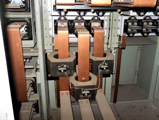
Figure 1 shows arcing damage after 3000:5 CT secondary leads were accidently cut during construction. CT was only lightly loaded in this instance and arcing across cables occurred lead to smoke and damage. Instances of accidental open circuiting of CT is unfortunately common during construction, modernization projects. Often damage goes unnoticed until after a smoke or fire incident.
Apart from wiring mistake and accidents, another cause of open circuit CT is rodent activity in the switchgear. Rodents like to chew on PVC wire eventually leading to cable damage and open circuit of CT. Since electrically nothing changes, nobody notices missing current reading on meter or relay until its too late.

What can be done to prevent accidental open circuiting of current transformer?
- Use ring lug when terminating CT leads. Ring lugs enhance the security and dependability of electrical connection.
- Equipment that vibrates (motors, transformers, generators etc.) can cause CT terminations to come loose over time. Suitable washers, torque nuts, double nuts may be used to prevent nut loosening.
- Use manufacturer recommended nuts and bolts to tighten CT terminations and be cautious of using dissimilar metals. Non-uniform metal expansion due to temperature change can cause connections to become loose over time.
- Install CT secondary leads in a dedicated conduit and properly identify them.
- Where CT leads are buried, use armored cable, and have reinforced covered cable trench.
- Use low power CT [LPCT] or Rogowski CT instead of iron core CT if the connected equipment can accept LPCT input. There is no damage risk with having an accidental open circuit on LPCT.
- Set current unbalance alarm function in the meter or relay to detect one or more phase current dropping to zero indicating open CT. Note this method is not useful when all three phase currents are lost.
- Use CT open circuit protector [OCP].
CT open circuit protector
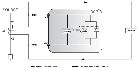
Open circuit protector [OCP] works by monitoring CT secondary voltage (between X1, X2 or S1, S2) continuously. During CT open circuit condition, if secondary voltage exceeds the set clamp voltage, (manufacturer and model dependent) a back-to-back connected SCR is triggered in to conduction reducing the voltage to around 2-35Volts (manufacturer dependent) in less than quarter AC cycle. The purpose of having a back-to-back SCR is to allow protection for both halves of AC cycle.
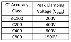
Clamp voltage is based on the OCP model number which is again based on accuracy rating [C Rating] of the CT. Table below shows typical peak clamping voltage for a particular vendor. Note that the clamping voltage is almost double the C rating voltage and hence using OCP won’t affect the CT saturation characteristics.
Under normal conditions, OCP has insignificant leakage current and does not affect CT accuracy or phase angle. OCP typically is also rated for short time overload current and is available in single or three phase models.
Apart from accidental open circuit of CT secondary lead, another area where OCP is useful is to protect CT from voltage transients. One way CT transient voltage can be generated is during capacitor bank discharge in to a fault as discussed in this article. OCP applied across CT secondary will limit the voltage and prevent CT damage. Note that a simple MOV type surge suppressor connected across CT terminals can only protect short duration transient voltage generated due to momentary fault or capacitor discharge. For open circuit CT, secondary voltage will be steady state and regular MOV will get destroyed in no time. OCP on the other hand has high current capacity SCR that will bypass the secondary current and protect the CT.
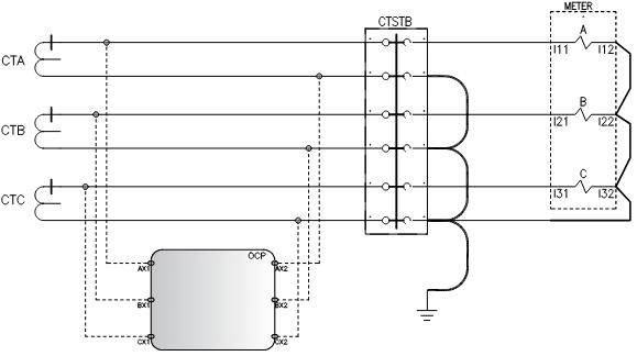
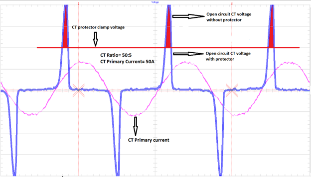
Simplified internal schematic of an OCP and connections for single phase CT is shown in figure 2. Connection diagram for a three-phase system is shown in figure 3. Waveform showing the actual open circuit voltage from a 50:5A CT and estimate on how the waveform would look like with an OCP is shown in figure 4.
Read: Neutral current CT
It is recommended that OCP be connected as close as possible to the CT and ahead of the shorting block.
Read: How to select taps for multi ratio CT?
Link to GE OCP