Flexible current transformer is also known as Rogowski coil. What is a Rogowski Coil? Rogowski coil is an electric current transducer that produces output voltage that is proportional to current being measured (eg. 1mV/A). Output can be connected to an oscilloscope or digital voltmeter for reading the current after suitable signal processing.
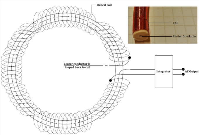
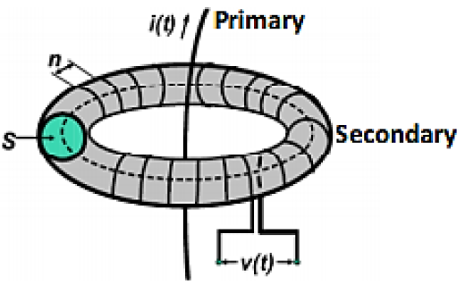
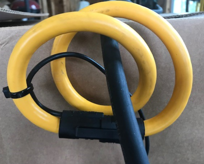
Flexible current transformer or Rogowski coil offers significant installation advantages over split core or iron core Current Transformers (CT) due to its lightweight construction, being very flexible, high current range. Strictly speaking Rogowski coil is a current ‘sensor’ or ‘transducer’ and not a current ‘transformer’. Rogowski coil can be considered air cored even though there is a flexible foam supporting the outer coil, see figure 2. One end of the wire starts off in a helical pattern while the other wire passes through the center of this helix and joins at the other end of the coil. The two ends of wire are brought out and fed to an integrator which coverts voltage signal produced by coil to proportional current signal.
Output of Rogowski coil is voltage proportional to current flowing in the primary circuit. Rogowski coils are available from small amperage (~30A) to around 100kA AC RMS. For measuring tens of thousands of amperes there is no better alternative than to use Rogowski flexible current transformer. Probes are available in lengths of 12 inches to 48 inches or more. Accuracy rating of commercially available probes is the range of +/-1% and phase accuracy (45-65Hz) is +/-1 degree.
Rogowski coil is also sometimes referred to as ‘Rope CT’.
Advantages of Rogowski Coil for current metering
- Wider bandwidth
- Ease of installation and removal
- Not bulky, Light weight
- Does not saturate
- Can be open circuited unlike traditional CT
Operating Principle:
When AC current flows through center of a closed sensor loop, voltage is induced at open ends of the secondary coil which is proportional to the rate of change of current.
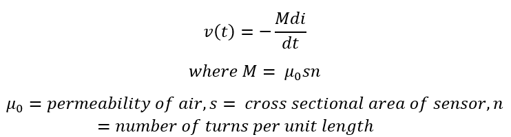
As can be seen, voltage measured at secondary is proportional to rate of change of current (di/dt) and is independent of the position of current conductor within the loop and loop need not be circular. To get current back, this voltage signal needs to be ‘integrated’ using an electronic integrator. This means that Rogowski can’t reproduce DC signal but can operate at low frequencies that traditional iron core CT may not be able to reproduce. Rogowski sensors can measure AC signals superimposed on large DC since coil itself is immune to the presence of DC current.
Advantages of Rogowski coil include highly linear output over a large dynamic range. Sensors are available that can be used in metering or protection applications. Since there is no magnetic core there is no CT saturation problem. Secondary leads can also be open circuited with no problems unlike traditional iron core CTs.
Read: Open circuit CT
Interference immunity
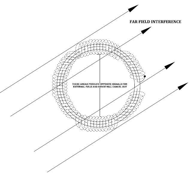
Rogowski coil can be built to be immune to external electric or magnetic interference. In many applications, interference will be far field, and the coil will produce opposing voltages and hence no voltage will be present in the output signal.
There is also other circuit modification that the manufacture can do to minimize external interference. However, Rogowski is not totally immune to noise. Rogowski coil amplifies noise because of the high gain integrating amplifier needed for the probe. Noise is predominantly below 1.5 kHz.
If external current (outside coil loop) is much greater than current being measured inside the coil, error may result. This is particularly important if the external current is flowing in a multi turn coil (transformer, reactor etc.).
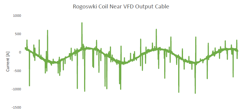
Similarly, if Rogowski coil is placed near sources of high voltage with high rate of change (dv/dt) then interference can arise due to capacitive coupling. Care should be taken when coil is applied in VFD, rectifier application with high dv/dt. One of the disadvantages of Rogowski coil is the amplification of noise.
Good paper on sensor resonance- Link
Practical tips with Rogowski flexible current transformers
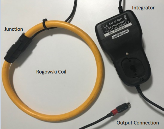
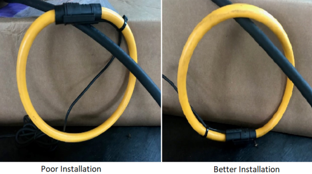
- It is best to install the coil around the primary conductor perfectly centered. However, in most applications this will not be practical to do. Next best practice is to install coil with junction facing away as far as possible from primary conductor, see figure 4. Having junction resting on the conductor will introduce additional measurement errors sometimes up to 4%.
- Avoid installing coil in vicinity of multi turn inductors (such as line reactor on a VFD) which could have large magnetic fields. Avoid installation near external conductors carrying current greater than what is measured.
- Avoid installing Rogowski coil in the vicinity of devices with large rate of change of voltage dv/dt (several 100V/μs). Example include output side of VFD or intermediate power stage of a large UPS. Large dv/dt can capacitively couple energy to Rogowski coil and lead to measurement errors or confusion. In such cases it is recommended to move the connection point further upstream.
- To check for unwanted responses, loop the sensor (without encircling the conductor to be measured) and while watching the reading on oscilloscope/meter move the sensor in the general area where the sensor will be located. If excessive noise current pickup is noticed, consider moving measurement location.
- For measuring currents at low end of sensor rating, accuracy and sensitivity can be increased by looping probe around the primary conductor twice, see figure 7. Scaling factor need to be adjusted accordingly. For example, if sensor is looped twice then scale factor should be divided by two.
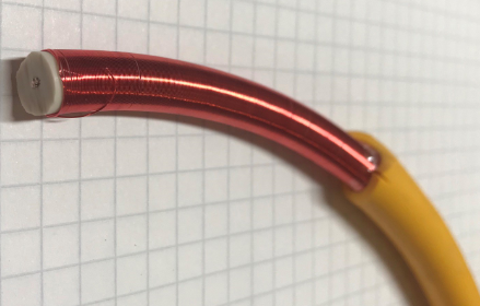
- Bending flexible coil more than the manufacturer recommendation for bending radius will introduce additional errors. This can also result some turns to permanently shift or even broken.
- If permanent current monitoring using flexible current sensor is planned, then confirm with manufacturer that the device is suitable for permanent installation.
- If Rogowski coil is installed permanently in high voltage application, then it needs to be made sure that corona will not occur. This is because corona will eventually destroy the coil insulation.
- Most flexible current sensors require an internal or external source of DC power supply. Consider the reliability and long-term stability of this source during the design phase of project.
- Passive battery less Rogowski coils are available but these have severely limited bandwidth performance.
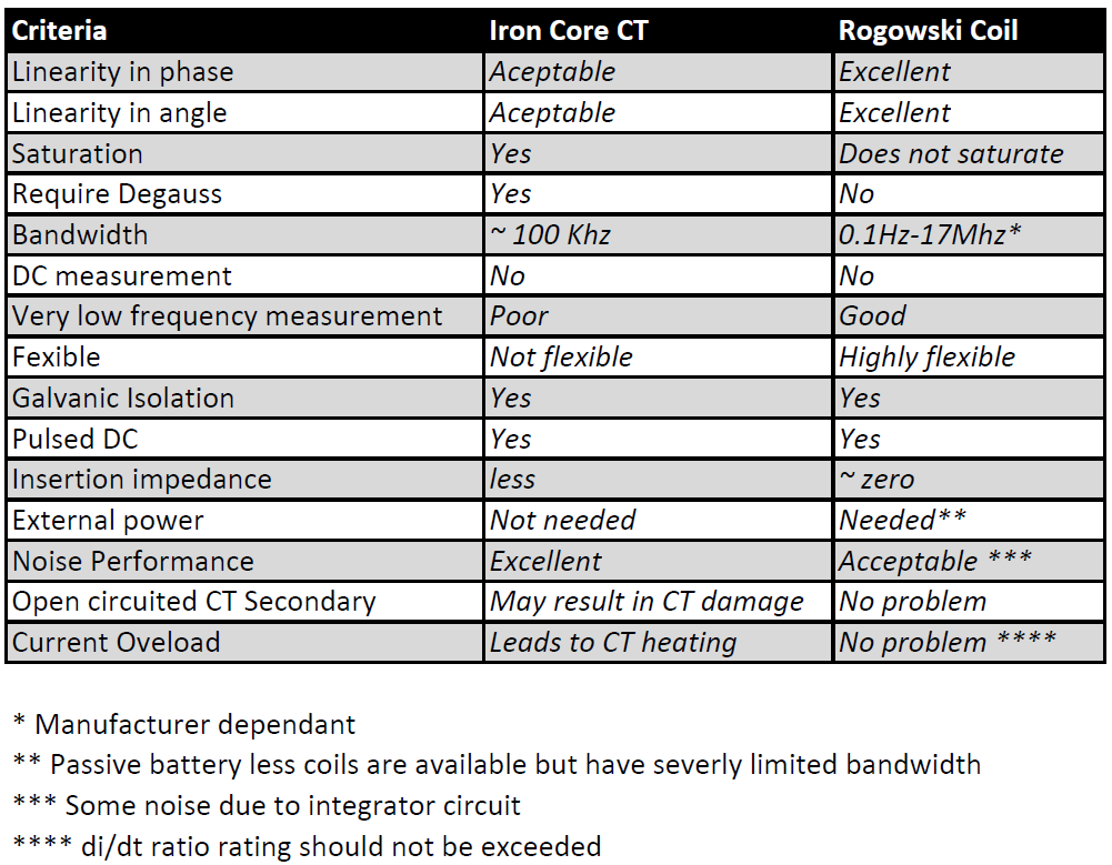
Iron Core CT vs Rogowski Coil
Comparison between iron core CT and Rogowski based flexible current sensor is given below.