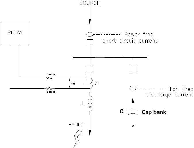
Current Transformer (CT) failure can be due to many reasons some of which are contamination, open circuit secondary, incorrect application etc. In this article, possibility of CT damage due to capacitor bank discharge current is discussed. Capacitor banks are applied at low, medium and high voltage to correct power factor and improve voltage stability. When short circuit occurs on or near the bus then capacitors can ‘discharge’ into the fault. These capacitor bank discharge currents are not at system frequency (50/60Hz) but are at hundreds of Hz to few kHz. Discharge current flowing through CT can create dangerous voltage at secondary side of CT which could damage CT insulation. Factors on which this secondary voltage depends are discussed.
Frequency of capacitor bank discharge current depends on system inductance and capacitance of bank. Peak discharge current into fault is given by:

In low voltage application, capacitors are typically ungrounded and maximum capacitor discharge current occurs for three phase external fault. In medium and high voltage applications, capacitors are usually solidly grounded, and maximum capacitor current occurs for three-phase to ground fault or single phase to ground fault.
Read: Phase to ground short circuit waveform
When high frequency capacitor discharge current flows, CT secondary voltage is given by:

From equation above it can be deduced that high CT secondary voltage can occur for:
- Large capacitor bank (Large Ipeak)
- Low inductance of interconnect bus, cable system (Large Ipeak)
- Low CT ratio
- High burden
Read: Kvar to uF calculator
The voltage that appears across secondary side of CT will also be present at all the devices that are connected to CT such as relays meters etc. If voltage rises to a magnitude higher than the insulation withstand capability of CT or devices connected, then damage may occur.
Read: How to identify capacitor switching transients?
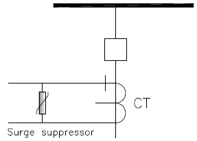
If it is identified that high voltage beyond the capability of CT or other devices connected to CT can be produced during a bus fault, then a surge suppressor may be connected across the CT terminals. These can be of metal oxide Varistor (MOV) type. The same concept is used in high impedance bus differential relaying where surge suppressor is employed inside the relay.
Read: High impedance bus differential relaying
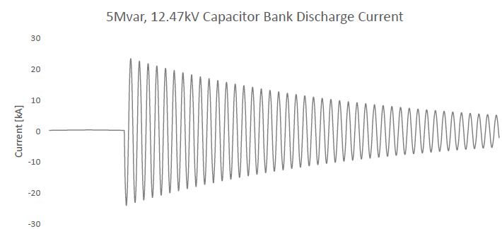
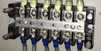
As an example, consider the waveform shown in figure 2 which is the discharge current from 5Mvar, 12.47kV bank connected as shown in figure 1. Peak discharge current is 23.5kA and the discharge current frequency is 8.5kHz. Consider CT to be 1200:5 which gives a CT ratio of 240. Assume total circuit burden of 0.5Ω. Using the equation given above, the voltage across CT terminals can be calculated to be 6.9kV peak. This voltage can be damaging to the CT insulation and other devices connected to the CT secondary circuit. Arcing across a CT shorting block is an indication of high voltage transient that occurred during short circuit fault.
Practically the presence of cable, bus inductance will help reduce the frequency of discharge current magnitude and frequency. If short circuit fault is very close to capacitor bank, then inductance will be minimum, and current magnitude and frequency could be high. If there are multiple banks, then each bank will contribute fault current. Capacitor banks with inrush limiting reactors will help in this situation. These banks will have series connected reactor in each phase and adds extra inductance in the fault circuit.