High impedance bus differential is a method of differential bus protection using parallel set of current transformers (CT) from each phase which is passed through a high impedance element in the protective relay. Under normal conditions, based on Kirchhoff’s current law (KCL), current into bus will be equal to current out of bus and no current flows through high impedance element. CT current simply circulate and no ‘differential’ current exists. When bus fault occurs, current is forced to flow through high impedance element in the relay creating a voltage drop. If voltage develop across the impedance is greater than the set value, relay will trip the breakers. This is the basic operation of high impedance differential relay.
Actual bus differential fault: Waveform Analysis
Relay impedance is usually purely resistive and is on the order of 2,000Ω to 2,500Ω. Metal Oxide Varistors (MOV) are connected across the resistor to clamp the voltage within the safe limits of CT wiring and relay. Some relays also include an overcurrent element which can be used as backup protection. Figure 1 below shows the operation of high impedance differential relay for normal load and during internal bus fault conditions. ANSI element for bus differential protection is 87B and high impedance differential protection is sometimes indicated as 87Z.
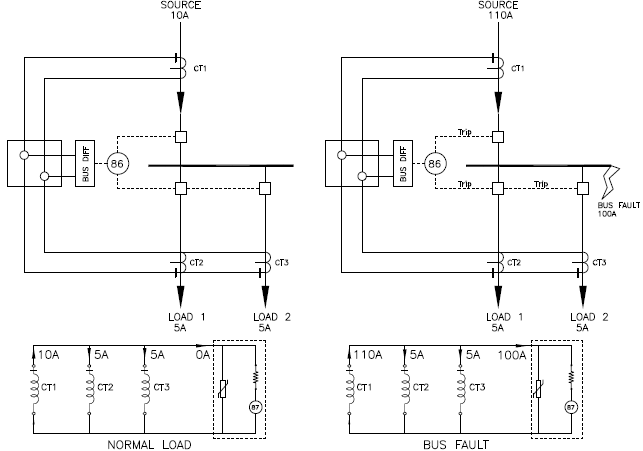
In figure 1 under NORMAL LOAD, CT current from the source and load CT will circulate among themselves and no current will flow through high impedance element. Under BUS FAULT condition shown on right side, fault current will flow through the high impedance element. If the voltage across the impedance is greater than the set voltage, relay will trip all the breakers.
High impedance differential protection setting calculation
High impedance differential relays are set in voltage. Setting for 87Z need to be low enough for ‘in zone’ faults while preventing nuisance tripping for ‘out of zone’ faults. Important parameters for setting relay are CT ratio, CT accuracy, fault current, resistance of CT and secondary leads and the number of circuits involved. Minimum voltage is determined by calculating maximum out of zone fault voltage and trip voltage is selected by multiplying minimum voltage by a safety factor.
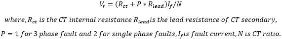
Minimum Voltage Setting: Relay trip voltage need to be set higher than voltage generated under the worst case ‘out of zone’ fault.
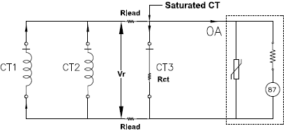
Worst case is usually at the load side of one of the feeder breakers. This out of zone fault is assumed to completely saturate one CT and hence its impedance is reduced to CT resistance + lead resistance. Other CTs are assumed to be not saturated. Equivalent circuit for CT3 saturated for an out of zone fault is shown.
Minimum setting needs to be:
Trip Voltage Setting
Relay trip voltage (Vs) need to be set higher than minimum voltage calculated by a factor of the ‘K’ safety factor. K value of 1.5 to 2 is usually used.

Translating voltage setting to actual pickup value
Once the high impedance differential relay pickup voltage is calculated, user may want to know what is the minimum value of bus fault current at which relay will trip. This value of fault current may be useful for other system studies. Minimum bus fault current for trip can be calculated as:
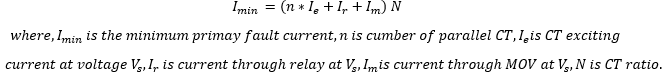
Looking at the equation, we can see that minimum pickup can be reduced (thereby making relay more sensitive) by reducing Ie which is accomplished by using higher accuracy class CT. Select CT ratio based on switchgear rating. Other parameters are not usually in system designers’ control.
Minimum pickup current can be used to identify the maximum load imbalance (due to open CT etc.) that relay can tolerate or maximum tapped load such as control power transformer or PT or PT secondary fault that relay can tolerate without tripping.
Application Considerations for High Impedance Differential Relay
CT Selection: Proper CT selection is important for reliable operation of high impedance differential relay. While a through fault may saturate CT, a bus fault almost always will result in CT saturation as the current is forced to flow through the high impedance.
Modern digital relays usually only need 0.25-0.5 cycle to determine if the fault is internal or external in spite of CT being saturated. Relay looks for area of the secondary CT waveform to make this decision. More the area, faster the decision can be made. Larger CT (large C value like C200, C400) will provide more area even under saturation. It is preferred that no less than C200 class CT be used for bus differential protection. Bushing or toroidal CTs with fully distributed windings and low leakage flux is preferred for this application.
Read: Open circuit current transformer
CT wires for each phase need to parallel with same polarity connected. It is also preferred that lengths to the common junction be equidistant (and preferably made in the switchyard). CT secondary leads need to be of sufficient gauge to minimize lead resistance.
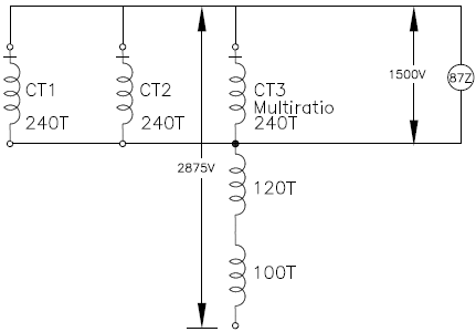
Multi ratio CT: Use highest tap available as lower taps have proportionally lower accuracy. All CTS in differential scheme need to have identical CT ratios. A larger CT can be used if the de-rated accuracy at its lower tap matches the accuracy of other CTs in the system. The unconnected taps can create dangerous overvoltage due to autotransformer action that the user needs to be cognizant of.
In the figure 3 it is assumed that MOV in 87Z limit voltage to 1,500V. Now, due to autotransformer action and based on turns ratio (100T etc) dangerous voltage could show up on unused taps of multi ratio CT. Due to fast operation of 87Z relay this is usually not a concern but this possibility need to be factored in to the design if multi ratio CTs are used.
Read: How to select correct taps for multi ratio CT?
Open circuit CT: An open circuit CT will cause a differential current to flow through the relay as soon as load is applied. Relay impedance is usually in the range of 2000-2500Ω. For this reason, it will only take very less current for relay to initiate trip. In other words, open circuit CT condition in a high impedance scheme will more than likely result in trip if load is present. A lower threshold can be set to provide CT supervision which will cause an alarm before trip occurs.
Short Circuit CT: Shorted CT on any of the circuit will disable the entire bus differential scheme since all CTs are connected in parallel. This usually happens when CTs are accidently left shorted during commissioning or testing. Shorted CT in bus differential scheme is hard to detect and it is encouraged that users remove all shorting screws prior to finishing the commissioning.
MOV degradation: MOV in the relay can degrade over time with repeated bus faults. If MOV becomes shorted, fault current will bypass the 87Z element and relay will not trip.
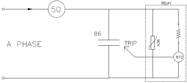
Under normal conditions, voltage across MOV will be zero and hence will be impossible to identify shorted MOV. If a series over current element (ANSI 50) is wired in series with 87Z then it can be used as a backup trip. It may be beneficial to inspect the MOV after repeated bus fault or if 86 lockout failed to operate during a bus fault. If 86 failed to operate, MOV will clamp voltage for a longer duration than necessary and will be prone to damage.
Shunt connected loads: Surge Arrestors, Voltage Transformers (VT), Control Power Transformers (CPT) etc. are some of the shunt loads that may be present in the bus differential zone. These loads draw inrush current when switched on or draw steady current during normal operation which can appear as differential fault current to 87Z relay. Typically, VT, CPT current draw will be too small to affect 87Z and can be ignored. It is recommended to evaluate the effect of VT/CPT secondary side short circuit on 87Z protection behavior. A small delay of ~1 cycle needs to be provided if MOV surge arrestor is in the zone. If older style gapped arrestors are used, then delay need to be atleast 2.5 cycles.
Conclusion: for successful high impedance differential protection, following needs to be considered.
*CT ratio and accuracy to be identical. Use high accuracy CT preferably C200 and above.
*Use bushing or toroidal CT with low leakage flux
*Minimize lead length and resistance with higher gauge CT secondary leads
*Distance from each CT to common point to be equidistant and as close as possible
*Consider ‘In zone’ loads- Auxiliary transformers, Surge arrestors etc.