The purpose of a Current Transformer (CT) is to produce an exact replica of the primary current waveform with its magnitude reduced in proportion to the turns ratio. CT is a very dependable and accurate device for the most part except when in goes in to saturation.
How does a Current Transformer saturate?
Current Transformer with a given core dimension can only support a given amount of maximum flux density in the core. As long as the flux density (flux in core created by CT primary current flow) remains below what the maximum flux destiny is, a change in flux will create a ratio current flow in secondary circuit.
When the primary current is so high that the core cannot handle any more flux, the CT is said to be in saturation. In saturation, there is no flux change when the primary current changes (as the core is already carrying maximum flux). Since there is no flux change there is no secondary current flow. In other words in saturation, all of the ratio current is used as magnetizing current and none flows in to the load connected to the CT.
Parameters relevant to saturation
- Cross section of the CT core: larger the cross section, lesser the chance of saturation.
- Quality and type of steel used to manufacture the core
- Burden: External load applied to the secondary of the CT is called ‘burden’.
Current Transformer Application Considerations
- CT primary current rating should be equal to or greater than the maximum expected current for the associated breakers or transformers.
- Maximum secondary current should not exceed 20 times the rated current (100A for 5A rated CT) for ANSI class C CT.
- Wye connected CT produces the rated CT secondary current on the external CT wires whereas delta connected CT produce currents that are 1.732 times the secondary current.
- Highest CT ratio that can be used a given application be used to get best performance. Too high CT ratio may be problematic for relays settings.
- For multi ratio CT, using a lower tap reduces the effective accuracy and increases the chance of saturation.
Read: Current Transformer DC Saturation and Time to Saturate
Current Transformer Performance Calculation
Current Transformer (CT) performance can be estimated using one of the following methods:
- Formula method
- Excitation curve method
- ANSI standards
Formula method
The formula method uses the fundamental transformer equation to calculate the effective flux density for a particular value of fault current. The calculated flux density is then compared to the capability of the steel used in the core of the CT and a determination is made whether the core will saturate or not for that fault current.
Obtaining the cross-sectional area and maximum flux density of the CT core is not easy and this method is only applicable in certain rare situations. This method is not discussed further.
Excitation method
Excitation curve represents a curve of CT secondary rms voltage plotted against rms current with the primary open circuited. The reasonably accurate secondary excitation curve for a given CT can be obtained by open circuiting the primary and applying AC voltage of appropriate frequency to the secondary. The current that flows in to the CT needs to be measured. The curve of applied rms terminal voltage vs rms secondary current is approximately the secondary excitation curve.
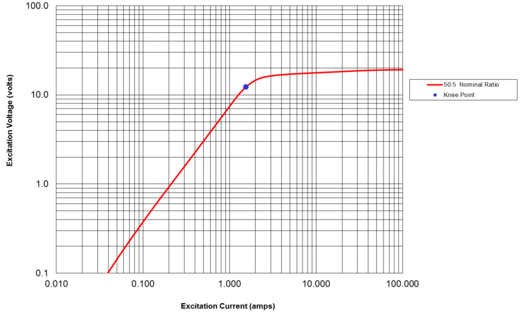
Example1: For a given 50:5 CT, the excitation curve is provided below. The relay connected to the CT should operate for 60A of symmetrical primary current. CT internal resistance= 0.0332Ω, lead resistance=1.25Ω, relay burden=0.5Ω. Calculate the actual primary current need to trip the relay.
Answer:
Number of turns =50/5=10
Relay operates for 60/10=6A of CT secondary current
When 6A flows in the secondary circuit the voltage drop Vs can be calculated as
Vs=6A*(0.0332Ω+1.25Ω+0.5Ω) =10.7V
Look at the excitation graph below the excitation current Ie for 10.7V of secondary excitation voltage is approximately 5A.
Total primary current=(60A+10*5A) =110A
Thus, the relay will only operate if the primary current is 110A instead of the desired 60A.
This can be improved by selecting a higher ratio CT. For example, by choosing a 100:5 CT with internal resistance of 0.064Ω and everything else remaining the same, the
Number of turns =100/5=20
Relay operates for 60/20=3A of CT secondary current
When 3A flows in the secondary circuit the voltage drop Vs can be calculated as
Vs=3A*(0.064Ω+1.25Ω+0.5Ω) =5.442V
Look at the excitation graph (not shown) the excitation current Ie for 10.7V of secondary excitation voltage is approximately 0.22A.
Total primary current=(60A+20*0.22A) =64.4A
Thus, the relay will operate if the primary current is 64.4A instead of the case with 50:5 CT which required 110A of primary current for relay to operate. The relay pickup current will be 61.6A if a 200:5 CT is used.
For calculations using excitation curve method it is important that the CT internal winding resistance is used in the calculation.
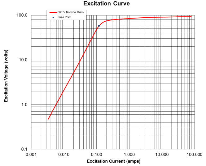
Example2: Excitation curve can be used to determine if a CT is adequate for a particular relay accuracy level from the excitation curve. This can be demonstrated using an example. Consider a 600:5 C100 CT. Assume the total burden including the CT winding resistance is 0.5Ω.
Solution: To check whether the relay is adequate, first calculate the secondary voltage at 20 times the rated secondary current.
![]()
From the excitation curve find the excitation voltage corresponding to 10A of excitation current. The reason for selecting 10A is because 10A is 10% of 100A and ANSI C current transformers guarantees 10% ratio error up to 20 times the rated secondary current. So for 100A of secondary current up to 10A can flow in to the magnetizing impedance and 90A to the burden and CT still meet the 10% accuracy requirement.
From the excitation curve below, for 10A of excitation current, the secondary voltage is 90V. Since 90V is greater than the calculated 50V the CT is adequate for the relay accuracy.
ANSI Standards
ANSI C57-13 relaying standard is described by two symbols- letter designation and a voltage rating. Examples are C50, C100, C400 etc.
The letters stand for the following:
C: Transformer ratio can be calculated
T: Transformer ratio must be determined by test
C classified current transformers (CT) have fully distributed windings and hence core leakage flux has negligible effect on the ratio. C classification covers bushing CT whereas T classification covers would-type transformers. For T classified CT the leakage flux is not negligible and affects the ratio appreciable. Only C classified CTs are discussed in this article.
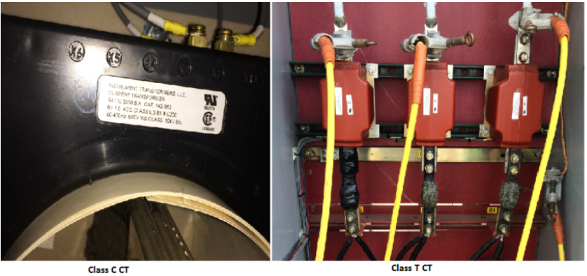
Class C and Class T Current Transformers
For example, C100 designation on a 100:5 CT indicates that ratio error will not exceed 10% between 1 and 20 times the normal secondary current if the secondary burden does not exceed 1Ω [1Ω*5A*20=100V].
Similarly, a C400 CT ratio error will not exceed 10% for a secondary current between 1 and 20 times the normal secondary current if the secondary burden does not exceed 4Ω. A popular rule of thumb is to have C rating twice the excitation voltage developed during maximum fault current.
Standard burden for relaying are 1, 2, 4 and 8 Ω with a power factor of 0.5.
![]()
ANSI accuracy class only applies to the full winding of the CT. If a lower tap is used then the burden that the CT can support without exceeding 10% error is proportionally reduced. This topic is discussed again at the end of this article.
ANSI standard burdens are defined at 50% power factor. The allowable burdens for various ‘C’ values are:
- C50: 0.5Ω
- C100: 1Ω
- C200: 2Ω
- C400: 4Ω
- C800: 8Ω
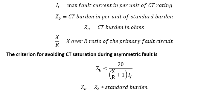
Avoiding CT Saturation During Asymmetric Faults
C rating assumes sine wave operation. When the power system experiences a fault there could be an asymmetric component to the short circuit current. This asymmetric current and the resulting decaying exponential current cause an increase in the ‘volt-time’ area and needs to be factored in to for avoiding CT saturation. IEEE/ANSI C57.13 standard for CT suggests that CT be applied at a location where the symmetrical fault current does not exceed 20 times the CT rating and the secondary voltage does not exceed the accuracy class of the CT.
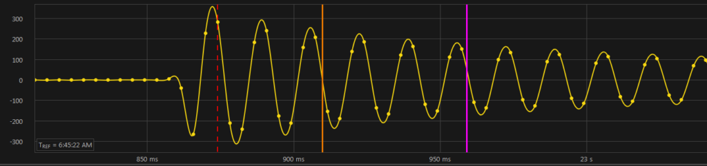
Asymmetric fault current
Preventing saturation due to asymmetric component of the fault current requires a C rating exceeding the C rating obtained for symmetrical fault current by a magnitude equal to X/R+1. However, achieving these ratings may be difficult in many practical installations.
The parameters to be considered for avoiding CT saturation under asymmetric faults are:
Example: A circuit has an X/R ratio of 5. The fault current is 25,000A. The selected CT is 2000:5 C100. The CT is connected with 100 feet (one way) of #12 SIS wire to the following devices.
- Relay1: 0.5VA burden
- Relay2: 0.1VA burden
- Meter: 0.05VA burden
Find out whether this CT will saturate for asymmetric fault current.
Solution:
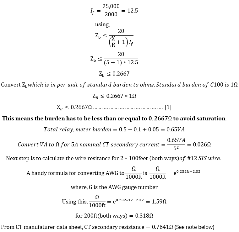
Note: It is acceptable to not use the CT secondary resistance when using this approach as the ANSI standard has already factored in the internal resistance of the CT for the C rating. However, CT internal resistance cannot be neglected when analysis is performed using detailed excitation curve method.
From [1] we calculated that the total secondary burden has to be less than 0.2667Ω to avoid saturation. Since the calculated burden of .344Ω is higher than 0.2667Ω this CT is not suited for this application and will saturate for an asymmetric fault.
Let’s See if a 2000:5, C400 CT will be suited for this application with the same fault current parameters.
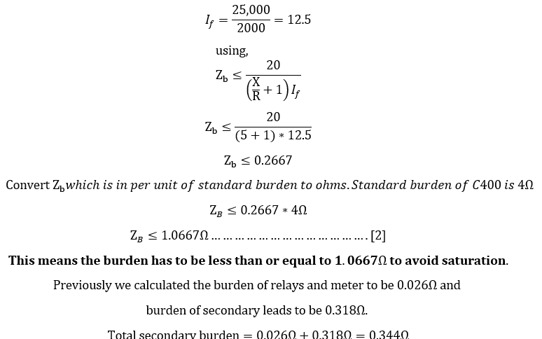
From [2] we calculated that the total secondary burden has to be less than 1.0667Ω to avoid saturation. Since the calculated burden of 0.344Ω is lesser than 1.0667Ω, CT is suited for this application and will not saturate for symmetric or asymmetric fault current.
Though the example above worked out well, it may not be possible to avoid saturation for situations with high X/R ratios or high fault current values. In those cases, it is best to size it as far as practicable and assess the effect of waveform offset on relay performance. For highly critical applications a transient computer simulation may be performed to assess the effect of DC offset on relay performance.
Multi Tap Current Transformer Burden
Multi tap CT offers multiple taps and hence offers different primary to secondary turns ratio depending on the tap that is being used.
Multi tap CT
What to do with unused taps on a multi tap CT?
Do not short the unused terminals of a multi tap CT as long as the chosen taps terminals are loaded/connected to a burden.
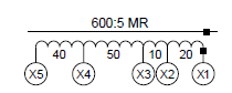
For the multi tap CT shown above, the various current ratings would be as follows:
600:5 X1-X5 500:5 X5-X2 450:5 X3-X5 400:5 X1-X4 300:5 X2-X4
250:5 X3-X4 200:5 X4-X5 150:5 X1-X3 100:5 X1-X2 50:5 X2-X3
Though multitap CT is very useful practically it has to be kept in mind that the accuracy class that is stamped on the CT name plate is based on the full rating of the CT. For the picture above, the C200 rating applies to 600:5 tap (full winding). Accuracy class reduces if a lower tap is being used.
How to select taps for a multi ratio CT?
Example: How do we calculate the new effective accuracy if a C400 3000:5 CT is used on a 2000:5 tap?
The new accuracy class for the tap can be calculated using the following formula:

Thus, a C400 CT will have an effective accuracy of C266 when a lower tap is used.
Example: How do we calculate the standard allowable burden if a C400 3000:5 CT is used on a 2000:5 tap?
The new permissible burden for the tap can be calculated using the following formula:
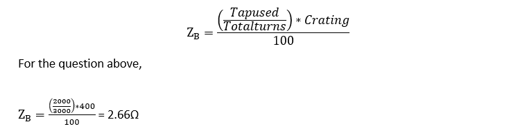
CT Terminology
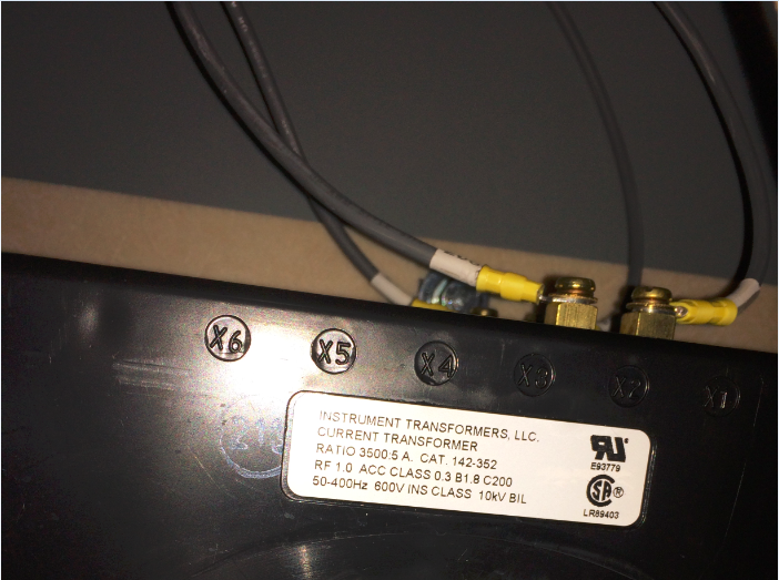
Common CT terminology as it appears on CT name plate are discussed below.
RF (Rating Factor): Rating Factor (RF) indicates the current carrying capacity of the CT. A 100:5 CT with an RF of 2 will be able to carry 200A of current continuously without overheating. The secondary current would also increase and be 10A for this example.
Knee Point: According to ANSI/IEEE the intersection of the excitation curve with a 450 tangent line is the knee point. IEC defines knee point as the intersection of straight lines extended from non-saturated and saturated portions of the excitation curve. ANSI knee is more conservative compared to IEC curve.
Accuracy Class: Accuracy class might refer to relay accuracy or metering accuracy. ANSI Relay accuracy is expressed in terms of C rating. See below for C rating definition. Accuracy class for metering application is provided as an example 0.3B1.8. This means the CT can supply the rated current to a burden of 1.8Ω and the ratio current will be within 0.3% accuracy. Accuracy of 0.3% is at 100% current and the accuracy drops to 0.6% at 10% of rated current.
C Rating: C rating is the secondary voltage across a standard burden (C100:1Ω, C200:2Ω etc) that the relay can support without exceeding 10% ratio error.
Frequency Range: Usable frequency range of the CT. Most relay class CT are rated from 50-400Hz.
Insulation Class: Low voltage CT are usually rated for 10kV BIL. Wound type class T CT usually have higher BIL rating.