Characteristics of a Phase to Phase Fault
Following are some of the characteristic ‘signatures’ of a phase to phase fault. See the oscillograph below to better understand these concepts. ![]()
Effects on Voltage
- Voltage phase angles of two faulted phases become similar
- Voltage decrease on the two faulted phases
- Voltage drop of approximately equal magnitude on both faulted phases
- No noticeable voltage drop on the healthy phase
Effects on Current
- Increase in current magnitude on two faulted phases
- 180-degree phase shift between currents of two faulted phases
- No substantial ground or neutral current
The following waveform were recorded on the 12.47kV side of a 10MVA 138kV/12.47kV substation transformer during a phase A-B fault on the overhead distribution lines feeding the city.
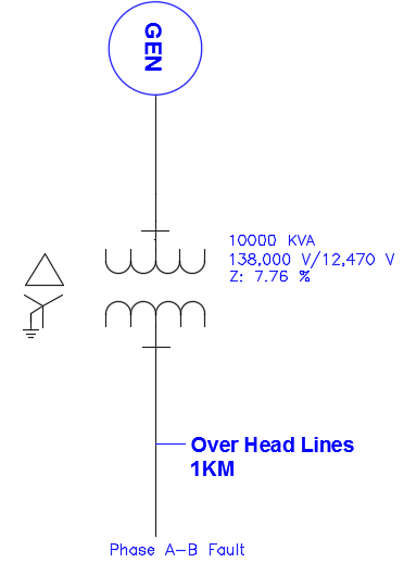
All of the characteristics noted above can be seen on the graph below except ground current which is not shown.
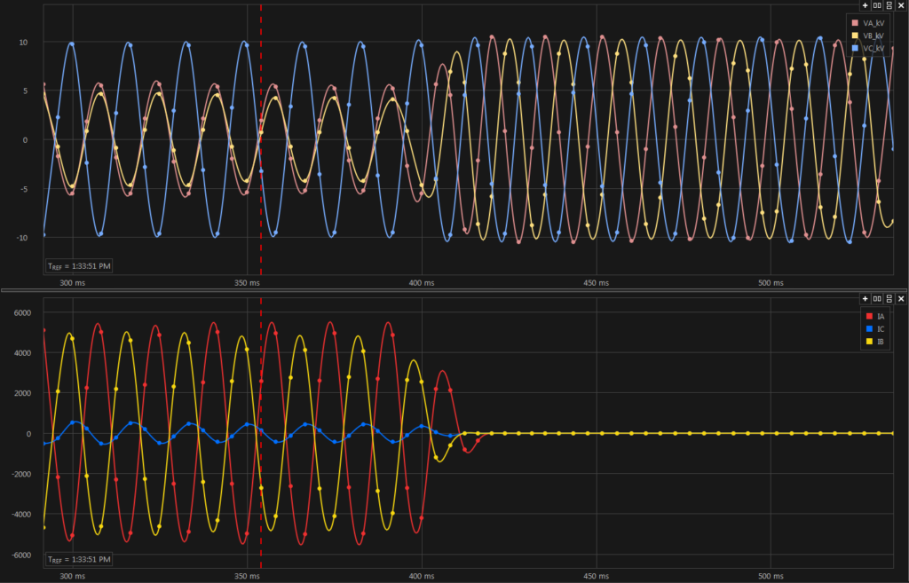
Phase to Phase Fault
Phase-Phase Fault (A-B). Note that voltage (top) phase angles become similar and current (bottom) phase angles are 180 degrees apart during the fault.
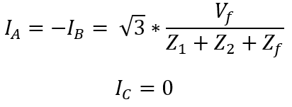
Sequence fault current for a phase-phase fault (Line to Line fault) is given by:
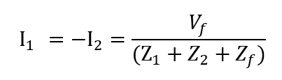
Where Vf is the per unit system line to neutral voltage (usually 1pu) and Z1 and Z2 are the positive and negative sequence impedance of the system and Zf is the fault impedance which could be zero for a dead short.
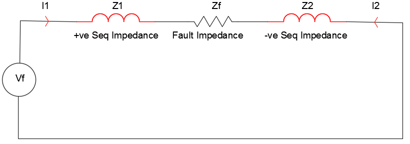
Phase to Phase Fault Sequence Diagram
From sequence components theory we can calculate the actual phase currents. The phase currents can be calculated from the sequence components using the following equations:
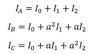
Calculating the actual phase current for phase A-B fault,
The fault voltage Vf is usually nominal line-neutral voltage of 1pu.
Current Distribution on a delta-star transformer during a phase-Phase fault
- Fault on the wye side
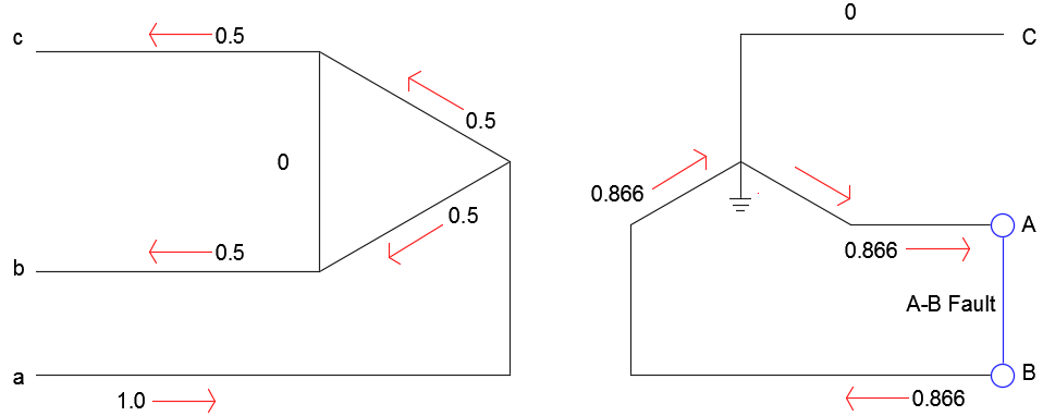
Fault on Wye Side
Assume the fault current for a three-phase fault on the wye (or star) side to be 1pu. Then for a phase-phase fault the current will be 0.866pu. If the line-neutral voltage on the wye side is 1pu, the voltage on the delta side will be √3 times that value.
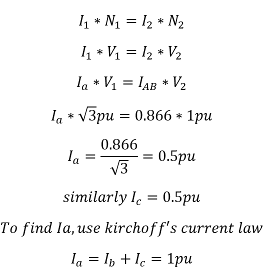
I1, N1 & V1 prefer to delta side and I2, N2 and V2 refers to wye side.
The fault current on the figure above are important for relay coordination purposes. From the results we can see that the relay on the wye side will see 0.866pu while the relay on the delta side will only see 0.5pu. It is necessary to factor in this data while coordinating relays on either side of a delta wye transformer.
- Fault on the delta side
Assume the fault current for a phase to phase fault on the delta side to be 3pu. The relative current magnitudes on the various phases on the wye side are shown in the figure below.
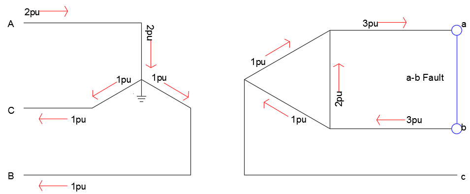
Fault on Delta Side
Additional Reading: Sequence Components