Characteristics of a Three Phase to Ground fault
Following are some of the characteristic ‘signatures’ of a three phase to ground fault. Characteristics of three phase fault will be exactly similar to three-phase to ground fault. See the oscillograph below to better understand these concepts.
Effects on Voltage
- Equal drop in voltage magnitude on all three phases.
- Only positive sequence voltage is present and very less to none of zero and negative sequence voltage.
Effects on Current
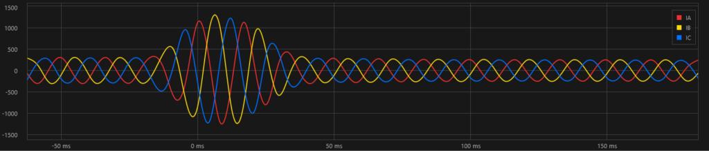
- Equal increase in current magnitude on all three phases.
- Very little to no ground current.
- Only positive sequence current is measured and very less to none of zero and negative sequence current.
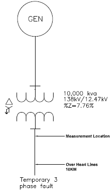
The following waveforms were recorded on the 12.47kV side of a 10MVA 138kV/12.47kV substation transformer during a distant three-phase fault on the overhead distribution lines feeding the city.
The waveform capture in figure 2 shows three phase fault which was cleared by another downstream protective device. Graph shows equal increase in current on all three phases indicating a three-phase fault.
During three phase fault, voltage on all three phases gets depressed relatively equally as shown in figure 3. At the fault location of a three-phase fault voltage will be depressed to zero volts. Since the measurement in figure 1 is taken at a location electrically distant (10KM away) from the fault point is the reason voltage is not depressed to zero volts.
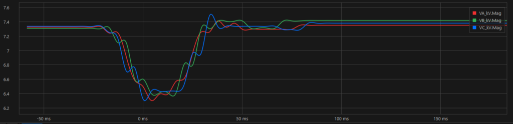
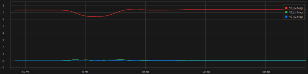
Figure 4 above shows sequence voltage during the three-phase fault. As can be observed, sequence voltage is entirely positive (V1) with no zero-sequence component and very little negative sequence component. A perfectly ideal bolted fault should only have positive sequence component and none of negative and zero sequence component.
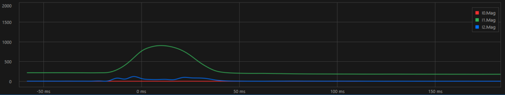
Figure 5 above shows sequence currents during the three-phase fault. As can be observed, sequence current is entirely positive (I1) with no zero-sequence component. There is few hundred amperes of negative sequence current which is probably due to the slight current unbalance between the phases. Negative sequence current can also arise if there is pre fault voltage unbalance on the grid.
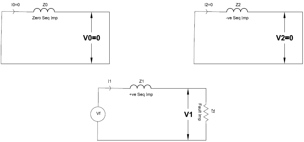
Sequence currents for a three phase-ground fault is given by:
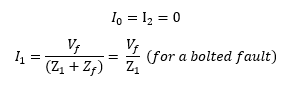
Where Vf is the per unit system line to neutral voltage (usually 1pu) and Z1 is the positive sequence impedance of the system and Zf is the fault impedance which could be zero for a bolted short-circuit.
Read: Sequence Components
From sequence components theory we can calculate the actual phase currents. The phase currents can be calculated from the sequence components using the following equations:
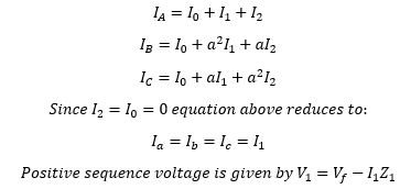
Only positive sequence voltage and current components are present in a purely three-phase to ground bolted fault. In the example graph notice that majority of sequence current is positive and there is only positive sequence voltage drop in the system. Practically three-phase faults may not be perfectly symmetrical from fault inception to extinguishing and may evolve from one type of fault and transition in to three-phase fault.
Link to: Phase to Ground short circuit waveform