Characteristics of a Phase to Ground fault
Following are some of the characteristic ‘signatures’ of a phase to ground or line to ground short circuit fault. See the oscillograph below and read the article to better understand the circuit behavior.
![]()
Effects on Voltage
- Drop in voltage magnitude on the faulted phase.
- A voltage rise or voltage drop on the un faulted phases. If the ratio of X0/X1 behind the fault is less than 1 then under voltage will occur on unfaulted phases. If the ratio of X0/X1 behind the fault is greater than 1 then over voltage will occur on unfaulted phases. If X0/X1 is unity, then no change on voltage magnitude on un faulted phases will be experienced. X0 and X1 refers to the zero and positive sequence impedance of the circuit.
Effects on Current
- High current on the faulted phase.
- High ground current.
- Appearance of negative and zero sequence current.
- Equal magnitude of positive, negative and zero sequence current.
Read: Sequence Components
The following waveform was recorded on the 12.47kV side of a 10MVA 138kV/12.47kV substation transformer during a phase B-G fault on the overhead distribution lines feeding the city. The fault then escalated in to a phase-phase(A-B) fault.
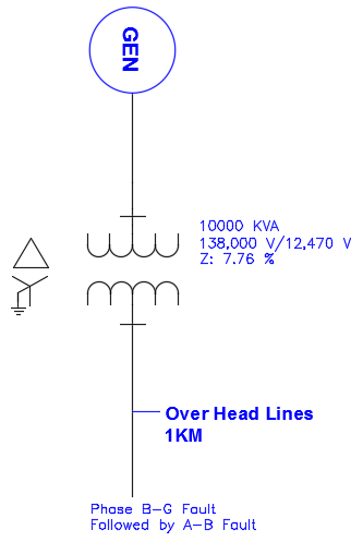
The waveform capture shows a phase-ground or line to ground fault which then evolved in to a phase-phase fault.
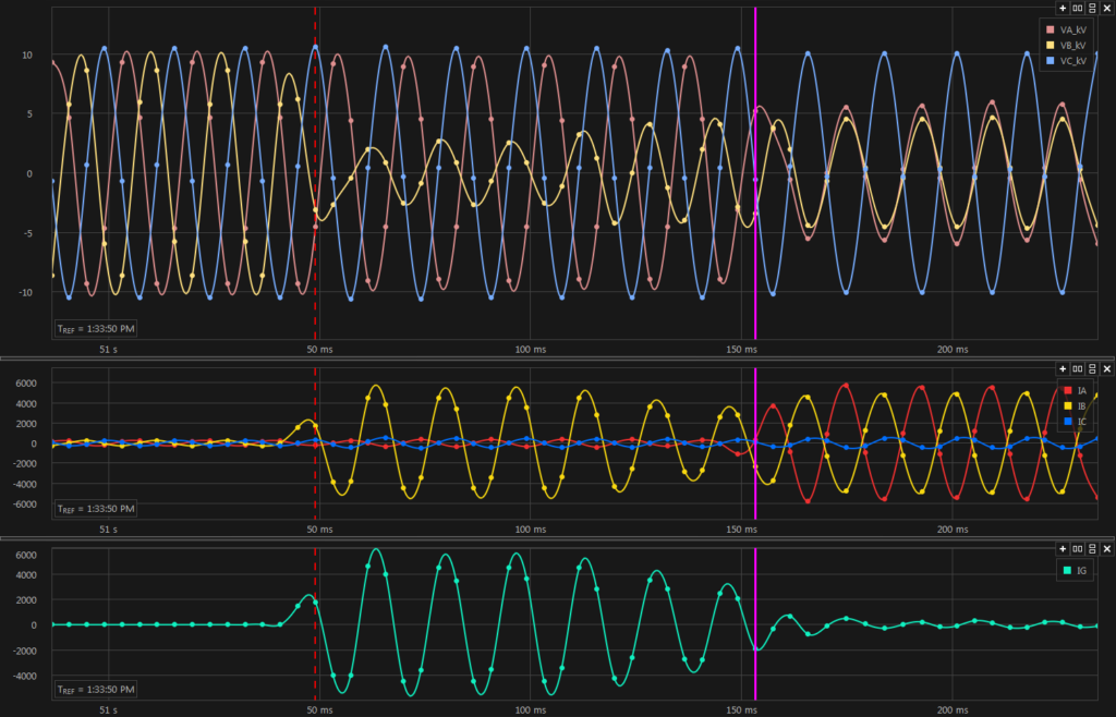
Phase to Ground and Phase to Phase Fault Waveform
Phase-Ground fault starts at dotted red cursor and ends at magenta cursor. Phase-Phase fault starts at magenta cursor. Top graph shows line voltage. Middle graph shows phase current and bottom graph shows ground current.
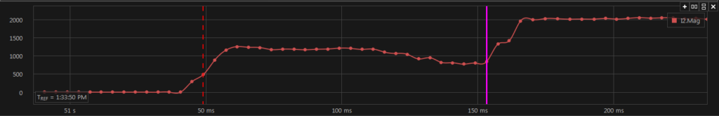
Negative Sequence Current During Phase to Ground and Phase to Phase Fault
Negative sequence current exists during a phase-ground fault and during phase-phase fault. Phase-Ground fault starts at dotted red cursor and ends at magenta cursor. Phase-Phase fault starts at magenta cursor.
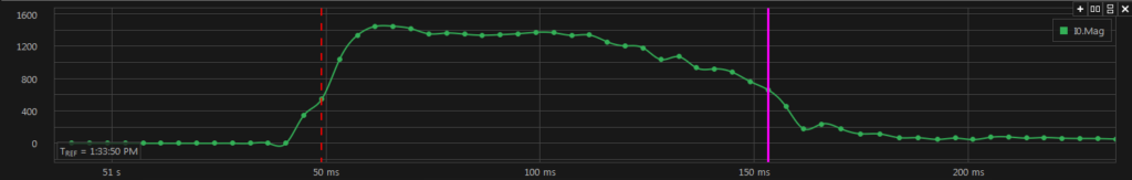
Zero Sequence Current During Phase to Ground Fault
Zero sequence current exists during a phase-ground fault only and does not exist for phase-phase fault. Phase-Ground fault starts at dotted red cursor and ends at magenta cursor. Phase-Phase fault starts at magenta cursor.
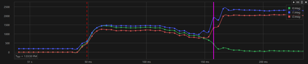
All sequence currents during L-G fault
During phase-ground fault positive, negative and zero sequence currents become approximately equal as can be observed on the above graph. The reason for this can be seen if the sequence impedance circuit provided below is studied. During the phase-phase fault, positive (I1) and negative (I2) sequence current becomes equal while zero sequence (I0) current disappears.
Also read Phase to Phase short circuit waveform
Sequence currents for a phase-ground fault (Line to Ground fault) is given by:
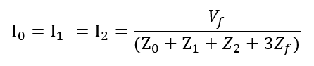
Where Vf is the per unit system line to neutral voltage (usually 1pu) and Z1, Z2 , Z0 are the positive, negative and zero sequence impedance of the system and Zf is the fault impedance which could be zero for a bolted short-circuit. Note that all three sequence currents are equal during a phase-ground fault.
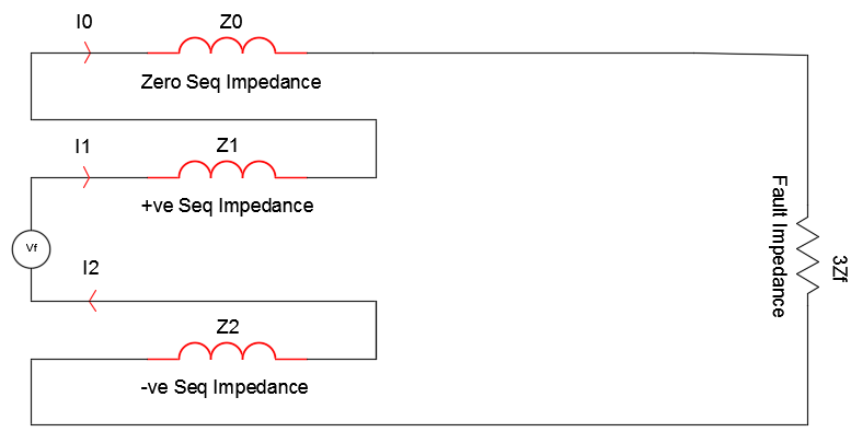
Phase to Ground Fault Sequence Diagram
From sequence components theory we can calculate the actual phase currents. The phase currents can be calculated from the sequence components using the following equations:
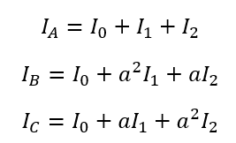
Calculating the actual phase current for phase A-G fault, from the sequence diagram above,
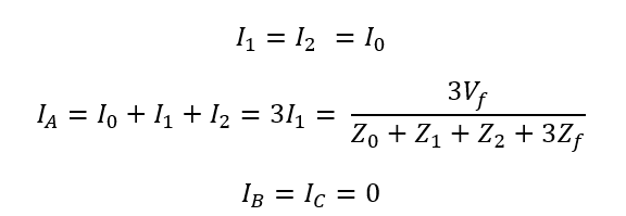
The fault voltage is usually nominal line-neutral voltage of 1pu.
Link to: Transformer full load and short circuit current calculator