Characteristics of a Double Line to Ground Fault or Phase to Phase to Ground fault
Double line to ground fault occurs when any two phases of the power circuit is short circuited to ground or neutral. Following are some of the characteristic ‘signatures’ of a Phase to Phase to Ground fault or Double Line to Ground fault. See the oscillograph below to better understand these concepts.
Effects on Voltage
*Voltage collapse on the two faulted phases.
*No significant effect on voltage on the unfaulted phase.
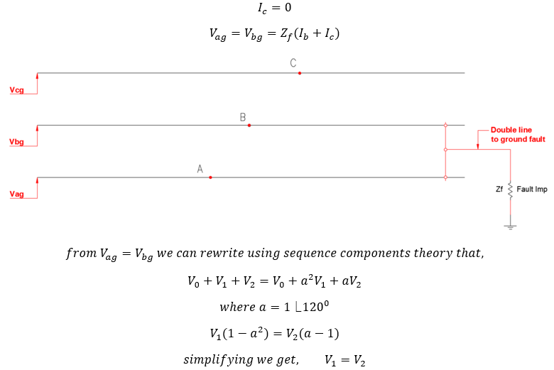
*Positive and negative sequence voltage becomes equal.
Effects on Current
*Increase in current magnitude of two faulted phases.
*Faulted currents maintain pre-fault phase angles (1200).
*Significant ground current flow.
*Presence of Positive (I1), Negative (I2) and Zero sequence (I0) currents.
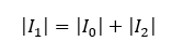
*Sequence Current: Magnitude of positive (I1) sequence current equals to sum of magnitude of negative and zero sequence current.
The following waveforms were recorded on the 12.47kV side of a 12MVA 125kV/12.47kV substation transformer during a phase A-B-GND fault on the overhead distribution lines feeding the city.
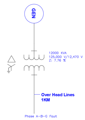
All of the characteristics noted above can be seen on the graph below.
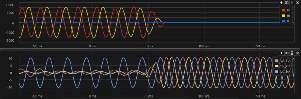
Double Line – Ground Fault (A-B-G). Top graph shows current and bottom graph voltage. Breaker trips around 60 ms and the fault is cleared. Observe the following: The faulted current (IA, IB) phase angles remain at 120 degrees which is the pre-fault phase angle. Voltage collapses on the faulted phases while the unfaulted phase (VC) voltage remains healthy.
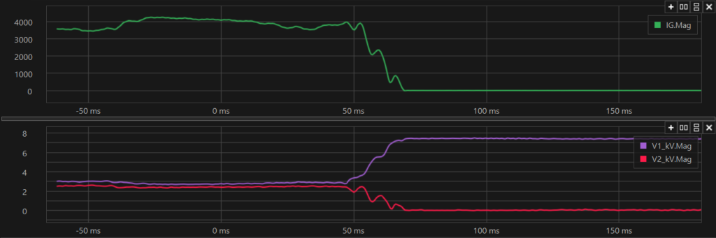
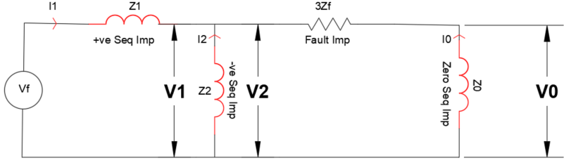
In above graph, IG is ground current (top) which shows significant rise in magnitude. Second graph plots positive sequence voltage (V1), negative sequence voltage (V2). Note that positive and negative sequence voltages (V1 & V2) becomes approximately same for the duration of fault. How the sequence voltages behave so can be seen by studying the sequence network diagram given below.
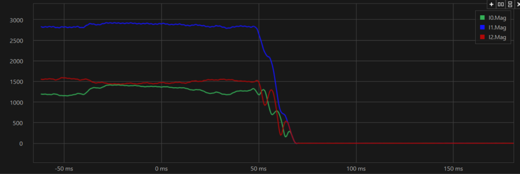
I0, I1, I2 are zero, positive and negative sequence currents respectively. Note positive sequence current equals to sum of negative and zero sequence currents. How the currents behave so can be seen by studying the sequence network diagram given below.
Sequence components of fault current for a double line to ground fault (Line to Line to ground fault) can be calculated as shown below:
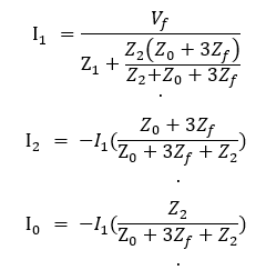
Where Vf is the per unit system line to neutral voltage (usually 1pu) and Z1 and Z2 are the positive and negative sequence impedance of the system, Z0 is the zero-sequence impedance and Zf is the fault impedance which could be zero for a bolted short circuit.
Observing the current flow, it can be seen that positive sequence current (I1) magnitude equals to sum of negative (I2) and zero sequence currents (I0) magnitude. The waveform above also shows this.
From sequence components theory we can calculate the actual phase currents. The phase currents can be calculated from the sequence components using the following equations:
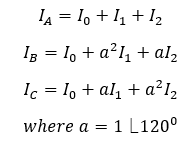
Assuming a phase A-B-Ground fault, we can write as follows:
The positive and negative sequence voltage becomes similar during the fault. This can also be observed on the graph above.
Link to Phase-Ground Short Circuit
Link to Phase-Phase Short Circuit
