Voltage Swell is defined by IEEE as increase in RMS voltage from 110% to 180% of nominal voltage at power frequency for durations from ½ cycle to one minute. Swells are less common compared to sags (dips) in power systems. Voltage swells can occur due to: Single line to ground fault, Load rejection, Addition of large capacitive kvar to the system etc. Single line to ground fault can result in voltage swell on unfaulted phases while load rejection and excess kVar results in three phase voltage swell. Excess kvar can result in steady state overvoltage condition if not mitigated. In this article only voltage swells due to line to ground faults are discussed.
Voltage swells can occur in grounded as well as ungrounded systems during a phase to ground fault and will persist for the duration of the fault. In ungrounded systems when a single phase to ground fault occurs there will always be voltage rise on the unfaulted phases. Line to ground fault in grounded neutral systems behave little differently.
Ungrounded Systems: Neutral inversion and Neutral Displacement
A line to ground fault on a grounded neutral system can result in one of the following on unfaulted phases a) Voltage Sag b) No change in voltage c) Voltage Swell. Grounded neutral systems refer to systems where the service transformer is wye connected and the neutral point of the transformer is solidly connected to ground (earth). The criteria for whether a swell occur or not is dependent on the ratio of zero to positive sequence impedance viewed from the point of fault towards the source.
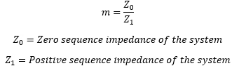
Let’s define a parameter ‘m’ which is the ratio of zero to positive sequence impedance of the system looking in to the source from the point of fault.
Depending on the value of ‘m’ the unfaulted phase voltage will sag or swell as follows. For the table below it is assumed that ‘A’ phase is the faulted phase and ‘B & C’ are the unfaulted phases.
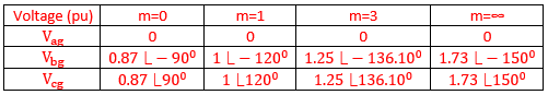
Case#1: m=0, which means the zero-sequence impedance of the system is zero (not applicable in real installations). Under this condition, unfaulted phases will experience a voltage sag of 0.87 per unit. Value of m=0 also establishes the minimum value of voltage sag on the unfaulted phases during a single line to ground fault.
Case#2: m=1, which means the zero-sequence impedance of the system is equal to the positive sequence impedance. Under this condition, voltage on the unfaulted phases will be 1 per unit. In other words, there will not be any change in the voltage for the unfaulted phases.
Case#3: m=3, which means the zero-sequence impedance of the system is three times positive sequence impedance. Voltage on the unfaulted phases will be 1.25 per unit. In other words, there will be a voltage swell of 1.25 per unit on the unfaulted phases.
Case#4: m=∞, An infinite value of ‘m’ means the zero-sequence current flow is blocked by a delta connected transformer or for other reasons. Under this condition, unfaulted phases will experience a voltage swell of 1.73 per unit. Value of m= ∞ also establishes the maximum value of voltage swell on the unfaulted phases during a single line to ground fault.
The last case of m=∞ illustrates the system behavior when system is ungrounded or high resistance grounded (HRG systems). Under these conditions, there is no or limited path for zero sequence current to flow. This will result in 1.73pu voltage rise for purely ungrounded systems and a value less than 1.73pu for HRG systems.
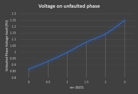
The maximum and minimum voltage rise possible in a grounded system is 0.87pu and 1.73pu as mentioned above. This can be graphically represented as below:
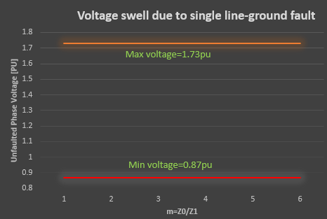
Note that figure 2 is applicable for both grounded and ungrounded systems.
Analysis of Voltage Swell during single line to ground fault on grounded system
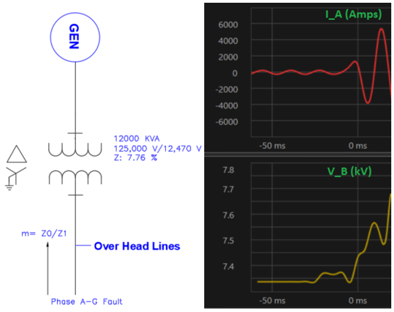
Below waveform was captured on a 12.47kV distribution feeder. Phase A to ground fault occurs around 0ms and almost immediately phase B voltage rises from 7.3kV (phase-ground voltage) to 7.68kV. The magnitude of voltage rise is 7.68/7.3=1.05 per unit.
Positive and negative sequence impedance looking from the point of fault towards the source is given in the table below:
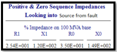
From the table, sequence impedance can be calculated to be Z0=1.53 and Z1=1.22. The ratio ‘m’ can be calculated to be 1.53/1.22= 1.25.
From figure 1 graph it can be seen that for a value of m=1.25, the expected voltage rise is 1.04pu. Let’s check if measured value matches calculated voltage. Pre fault measured voltage = 7.33kv, calculated voltage rise= 7.33*1.04= 7.62kV and actual measured voltage rise=7.68kV. Calculated value closely matches the measured value.
Voltage swell effects
Though less common compared to voltage sags, swells do occur and can cause disruptions to the process in an industrial facility. Some of the common problems associated with swells are: Arrestor failure, MOV failure (in surge suppressors), VFD overvoltage fault, overvoltage stress damage to sensitive electronics, PLC /Computer reboots etc.
Voltage swell mitigation
Mitigation of voltage swell is a challenge because it is a natural byproduct of system behavior during a fault, load rejection, capacitor bank switching etc which are the common causes of voltage swell. Each of these are discussed below along with possible mitigation solutions.
Fault: Voltage swell can occur during line to ground fault on grounded or ungrounded systems. For ungrounded systems the maximum line-ground voltage swell can be 1.73 per unit. For grounded system the swell will be typically much less than 1.73pu and will depend on system sequence impedances. It can be safely said that a grounded system always yields lower voltage rise due to a L-G fault compared to ungrounded systems and should be chosen if phase-ground voltage swell cannot be tolerated.
Load rejection: When a large amount of load (kW) is instantly disconnected from the system, temporary voltage rise can occur until the system stabilizes itself. Load rejection result in three phase voltage swells. This can happen for example in heavy industrial applications when thousands of horsepower motors are tripped offline for any reason. The solution here will be to slowly ramp the load down which may not be possible always.
Capacitor bank: By switching the least amount of kVar needed at any given time, voltage rise can be kept under control. Likewise, when the kVar demand is less the excess capacitive kVar needs be taken out of the system by switching off the banks. This can be done using a capacitor bank stage controller. If necessary, fast acting thyristor switched banks or active power factor correction may be installed. Excess kVar result in three phase voltage rise.
Few other mitigation solutions to avoid process upset due to voltage swells are:
*Rate the arrestor/MOV for the expected maximum line-ground voltage
*Do not set VFD overvoltage settings too sensitive
*Ensure VFDs are rated for the source grounding scheme
*Use power conditioning devices (UPS etc) to back up sensitive electronics.
*Use Ferroresonant constant voltage transformer backup for sensitive electronics