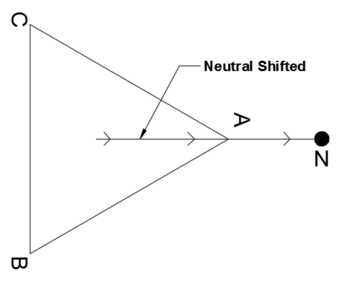
Neutral inversion, Neutral shift or Neutral voltage displacement is the phenomenon in which the imaginary neutral of an ungrounded system falls outside the voltage triangle. For a perfectly balanced ungrounded system, the imaginary neutral point will be inside the voltage triangle and at equal magnitudes from the phase voltages.
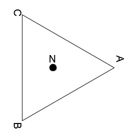
Delta System neutral
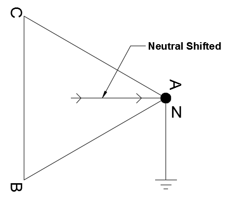
To understand this phenomenon, it is necessary to keep in mind that for an ungrounded three phase system, even though the neutral point is ungrounded, the system is ‘effectively’ grounded through the line capacitance. See figure below.
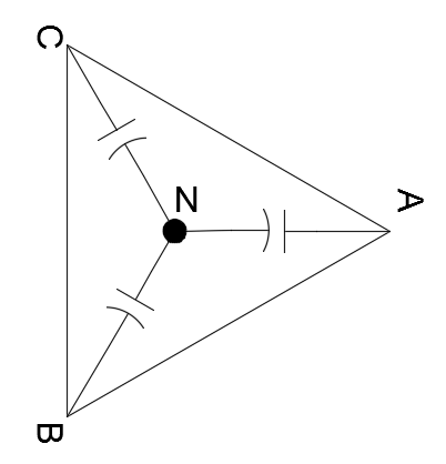
Delta System showing capacitively coupled neutral
The ungrounded system could be delta or wye with neutral ungrounded. When the line to ground impedances (usually capacitive impedance) is not equal between the phases, the position of neutral inside the voltage triangle could change or in the worst case fall outside the triangle. Stated in other words, neutral inversion or neutral displacement can occur in a system with unbalanced impedance to neutral in system with balanced set of three phase voltage.
How does unbalanced impedance arise?
In a perfectly transposed line or a three-phase cable in perfect trefoil formation, each phase conductor will have the same capacitance to ground. Hence there will be no potential difference between neutral point of supply transformer and neutral point of the ungrounded system. As mentioned above, the cause for neutral inversion or neutral shift is unbalanced impedances on different phases to ground. These unbalances can arise due to different reasons such as:
- Transmission lines that are not transposed which results in unequal impedances (both inductance and capacitance).
- Single core cables installed over long distances in a flat or otherwise non-trefoil formation.
- Single phase Voltage Transformer (VT) connected at one phase to ground. These VT could be used for metering relaying or deriving a synchronization voltage.
Neutral Inversion or Neutral Displacement
If any of the above bullet points are applicable, the neutral point could be shifted or in the worst case be inverted and located outside the voltage triangle.
Consider a three-phase ungrounded delta system with a single-phase voltage transformer (VT) connect line -ground on A phase. Additionally, assume the VT is unloaded on the secondary side or has very low burden on the secondary side.
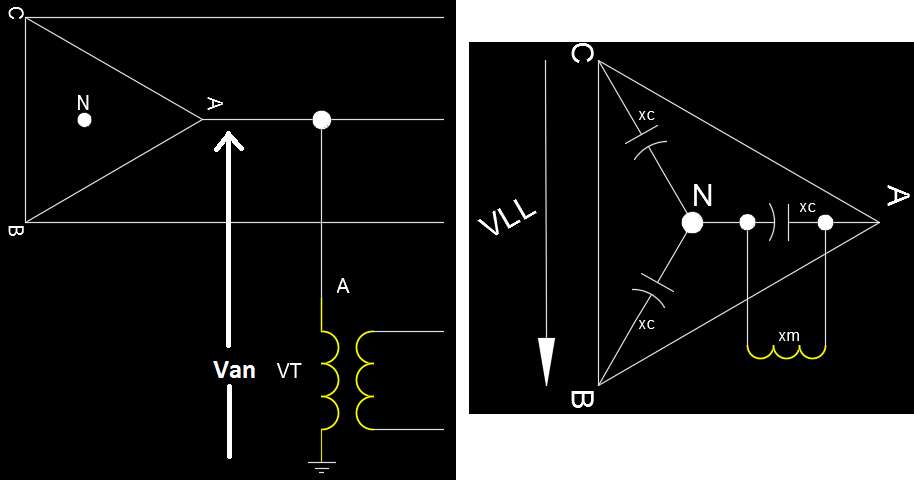
Unloaded single-phase VT on a delta system
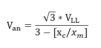
The effective voltage across phase A to ground (Van)can be calculated to be:
Van= Phase a voltage to ground
VLL= Line to Line (Phase-Phase) voltage
xc=Distributed capacitance per phase
xm=Magnetizing impedance of the voltage transformer
The equation neglects resistance which is a reasonable assumption in medium or high voltage conditions as inductance dominates the impedance equation.
From the equation above it can be seen that when the ratio of xc/xm equal to 3 theoretically an infinite voltage can arise across the VT. However, this will not occur in practice as the increase in voltage will result in VT core going in to saturation and as a result, xm decreases.
When xm= 0.787xc, from the equation above Van=VLL .
When xm< 0.787xc, from the equation above Van>VLL and neutral could fall outside the delta voltage triangle. This is the basic mechanism of neutral inversion.
Neutral Inversion or Neutral Shift
How to mitigate neutral inversion in Voltage Transformer (VT)?
Modern microprocessor based relays and other instruments have extremely low burden. This is part of the reason that the neutral displacement and neutral inversion has been observed at many installations. In instances where single phase VT is applied in a ungrounded system, it is recommended to resistively load the VT with a burden resistor. Resistors size must be engineered to provide the required burden for the VT. Manufacturer may have to be contacted to get suggested burden. Care must be taken while loading the VT especially if VT is used in metering or synchronism check application as loading the VT above a certain % of its VA rating will result in phase shift or phase error. Usually the VT is loaded between 20-30% of the VA rating of the VT and is a reasonable compromise between providing sufficient burden and providing good phase accuracy.
VT loading is also used to prevent ferroresonance in installations with three phase grounded wye VTs installed on a ungrounded system. Usually VTs are loaded 20-30% of its VA rating for ferroresonance mitigation in these applications.
Neutral Inversion at tail end of long transmission lines
Presence of a VT is not absolutely necessary for neutral inversion. Unequal line impedances (inductances and capacitances) in the system also can theoretically lead to neutral inversion. However, to achieve that the conductors have to be extremely long (> 200 miles) and not transposed.
On long transmission lines, Z1 (positive sequence impedance) and Z2 (negative sequence impedance) increases linearly with distance whereas Z0 (zero sequence impedance) decreases. The capacitive charging current at the tail end of the lines must flow through the series reactance of intervening sections, causing zero-sequence voltage to rise towards the tail end of the line. This can result in neutral being outside the delta voltage triangle. Again, this is a problem that could occur when line lengths are very large (>200 miles).
Neutral Shift during Line-Ground Fault on Ungrounded Systems
In the previous topic, the neutral displacement that can happen on long transmission lines is discussed. Neutral can also be displaced if there is a ground fault on an ungrounded system.
Consider a delta connected 480V source, with the imaginary neutral formed by stray capacitance at the center of the triangle. In this ideal situation, phase A, B, C will have 277V to the imaginary neutral at the center of the triangle. When a line-ground fault occurs say on A phase, the A phase-ground voltage will collapse to zero.
Neutral shift during a line-ground fault
Now, the voltage from phase B and C to neutral is the full phase-phase voltage 480V instead of 277V. This is due to neutral being shifted from the center of the triangle to one of the corner.
Another phenomenon that can be of serious problem is arcing ground fault on ungrounded systems. Arcing ground faults can cause large transient overvoltage due to random and unpredictable position of neutral during arcing. Due to the inherent stray capacitance interacting with arcing current, large magnitude of voltage oscillations can be observed which can damage sensitive equipment.
Neutral Shift during Line-Ground fault on Effectively Grounded Systems
An effectively grounded system according to AIEE standards No. 32, May 1947 is ‘A system or portion of a system can be said to be effectively grounded when for all points on the system or specified portion thereof the ratio of zero-sequence reactance to positive-sequence reactance is not greater than three and the ratio of zero-sequence resistance to positive-sequence reactance is not greater than one for any condition of operation and for any amount of generator capacity’.
Depending on the ratio of X0/X1, the line to ground voltage could vary between 0.6 to 2.0 times the normal line-neutral voltage during a line-to-ground fault.
Once the system X0, X1 ratio is known, there are charts available that can provide the estimated rise in neutral voltage. Electrical Transmission and Distribution Reference Book is an excellent resource for this. Tables are provided in chapter 14, figure 6 of this book.
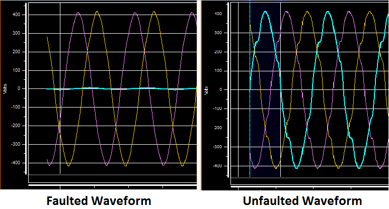
How to visualize neutral inversion or neutral voltage displacement?
Visualizing and analyzing neutral inversion or neutral voltage displacement is not straightforward as looking at a waveform. The example below shows an unfaulted waveform (normal case) on the right and a faulted waveform on the left. It is not apparent by looking at the waveform how much neutral displacement has occurred.
The best way to visualize neutral displacement is by looking at phasor diagrams. Here again we have a problem since most phasor displays on meters, relays and on computer software are based on displaying one cycle of three phase voltage and its relative phase angles. This is not very helpful to us in visualizing the neutral voltage displacement.
Note: Usually relay picks up phase A voltage as the reference phasor and all other angles will be relative to phase A voltage. If voltage is not available relay may pick phase A current for phasor reference. When working with software it may be possible to pick your reference voltage or current channel.
Neutral voltage displacement is best visualized by generating phasor diagram for faulted and unfaulted cases (using Microsoft excel or similar) and superimposing the two phasor diagrams. See below the phasor diagram generated for the waveforms above.
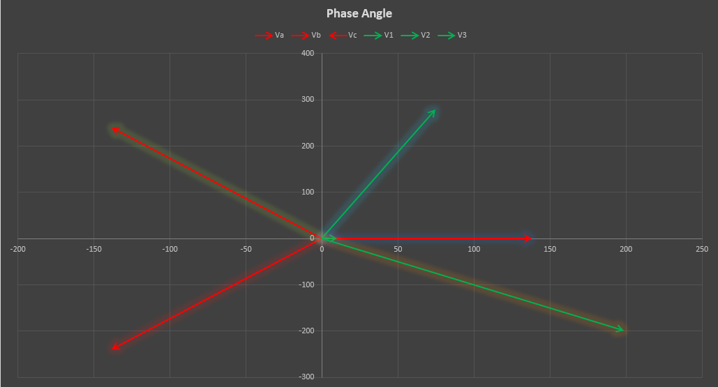
Phasor diagram with faulted and unfaulted phasors superimposed
By drawing a triangle around the normal (red) phasor, we can calculate the neutral point under normal case. This will be the zero point at the center of the above plot.
Similarly, a triangle be drawn around the faulted (green) phasor end points. The center point of that triangle will be the neutral point when the system is faulted. By measuring the distance between the two neutrals we will get the neutral voltage displacement.
How does neutral inversion compare to ferroresonance?
Ferroresonance has strong similarities to neutral inversion in that both involves interaction of stray capacitance of conductors interacting with transformer magnetizing reactance (resulting in ferroresonance) or magnetizing reactance of a single-phase VT (resulting in neutral inversion or neutral shift). Both are similar in certain ways though there are important differences as well.
Ferroresonance can occur with or without neutral inversion. Similarly, neutral inversion can occur with or without ferroresonance. However, there are strong similarities in underlying interactions that creates both phenomenon. Some of the solutions to mitigate neutral inversion in VT circuits are also use in mitigating ferroresonance issues in VT and transformer circuits.