What is a Ferroresonant transformer?
Ferroresonant transformer also known as Constant Voltage Transformer (CVT) is used to provide:
-
Voltage sag mitigation
-
Voltage regulation
-
Common mode and differential mode attenuation of power system noise
-
Transient voltage attenuation
In addition to providing above benefits, CVT also provide line isolation and some models come built in with additional output transient voltage suppression. CVT has been in existence for many decades and much longer than modern voltage stabilizers came to the market. Even though the technology is old, CVT continues to be used as it has some advantages.
In industry Ferroresonant transformers (CVT) are used in application that could be negatively affected by voltage sags (voltage dips) in the power system. Example of some of these applications include:
-
Power supply for critical PLC circuits
-
Power supply that is part of E-Stop circuits
-
Power supply for process computers, other critical infrastructure
Ferroresonant transformer theory
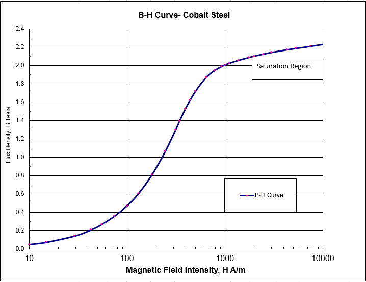
Ferroresonant transformers (CVT) uses a transformer core that is operated in saturation. This means a change of magnitude of flux density is relatively independent of the magnetic flux inside the core. Normal power transformers are not operated in saturation as this is not very efficient. Since the transformer core is operated under saturation, small change in input voltage do not cause any significant change in the output voltage.
Secondary circuit of the CVT comprises of a resonant tank circuit. If the resonant tank circuit is not present, the output voltage will be a square wave with high harmonic voltage distortion. By adding the resonant circuit, a quasi-sine wave voltage can be obtained. If sinusoidal output is desired, a ‘harmonic neutralized’ design should be specified which will provide a voltage distortion of 3% or less.

Picture Source: http://powersupply.blogs.keysight.com
Advantages of Ferroresonant Constant Voltage Transformer (CVT):
-
CVT has excellent voltage regulation when the RMS load current is constant or slowly changing.
-
CVT is inherently short-circuit proof. If the output leads are short circuited, a high current of 1.5-2 times the rated current would flow in the secondary circuit and this will not harm the transformer. In this instance the transformer will act as a constant current source.
-
Brief loss of input voltage for 2-4ms will not result in any change in output voltage. This is because during the brief interruption period the resonant circuit will continue to supply the necessary load current.
-
The resonant circuit in the CVT provide larger differential mode attenuation compare to typical LC filter modules in the frequency range below 10KHz.
-
Provides some common mode noise attenuation.
-
CVT using Ferroresonant circuit has few components and has high reliability. There are no moving parts or semiconductors in the basic design.
-
Loads connected to CVT receive protection from transient voltage.
-
Sine wave output for harmonic compensated type CVT.
-
Voltage THD < 3% for harmonic compensated type CVT.
Disadvantages of Constant Voltage Transformer (CVT):
-
Since the transformer core is always operated under saturation, this is an inherently inefficient design. The core operated at a high temperature of around 45 to 850 C above the ambient owing to the power dissipated in the core.
-
The Ferroresonant transformer has air gap in the core that can radiate relatively large time varying magnetic field. Devices sensitive to magnetic field should be kept some distance away from the transformer.
-
Ferroresonant transformer produces audible hum.
-
Resonant circuit inside the CVT has a fixed tuned oscillating frequency. As such the device is sensitive to changes in frequency of input waveform. For a typical Ferroresonant transformer, if the input voltage changes by 1%, the output voltage will change by about 1.5% to 2%.
-
CVT occupies larger footprint compared to regular transformers of similar size.
As mentioned before Ferroresonant Transformers (CVT) when short circuited functions as a constant current source. This is a disadvantage when CVT is feeding large electronic power supplies which draw current in ‘pulses’ near the peak of the AC voltage waveform. Hence it is suggested that the CVT be sized larger than the VA rating of the load sometimes up to twice larger than the load VA.
Ferroresonant Transformer Waveform
The input and output voltage waveforms for a 60VA ;Harmonic Neutralized’ type CVT is provided below. As can be observed, the voltages are fairly similar with the CVT output voltage lagging the input voltage by 30 degrees.
It was measured in this instance that the voltage total harmonic distortion was less than 3%.
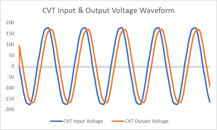
CVT input and output voltage waveform with linear load
Below is a test setup for a 60VA constant voltage harmonic neutralized CVT. The name plate of the CVT is:
Input Voltage: 95-130V
Output Voltage: 118V
Frequency: 60Hz
VA: 60
Type: Harmonic Neutralized Type
Various tests are performed to check the performance of the unit as compared to the nameplate specification:
The following tests were performed:
-
No-Load test
-
Load test- Linear Load
-
Load test-Non- Linear load
-
Transient Injection Test
1) No-Load test
The input voltage is varied from 30V- 150V and the output voltage is measured with no load connected to the CVT.
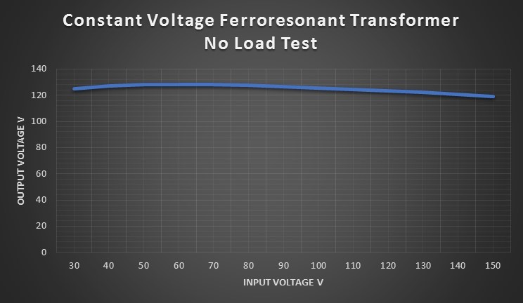
CVT No Load Test
Note that the output voltage quickly picks up to 120V even with only 30V applied on the primary. Note that this is with zero load on the transformer. Also noticed is the CVT regulates the output voltage with a high degree of regulation. For an input voltage variation from 30V to 150V, the output voltage only varies from 125V to 119V. Note that when the CVT is loaded, regulation will only happen close to its rated voltage and not necessarily at very low voltages (30V in this case).
2) Load test- Linear Resistive Load with unity power factor
In this test, the CVT is loaded with a linear resistive load with unity power factor. The load applied is 70% of its rating (60VA) and the input voltage is varied from 30-150V.
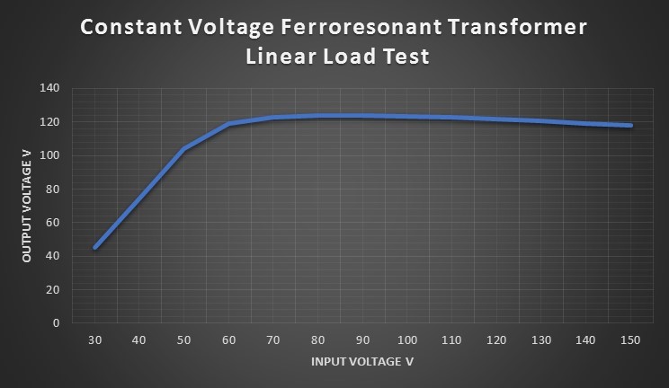
CVT Linear Load Test
Note that the output voltage is constant over the specified input voltage range and even above and below its rating. The Ferroresonant transformer here is rated for 60VA with rated voltage 95-130V AC, 60Hz.
3) Load test- Linear Motor Load
In this test, the CVT is loaded with a linear motor load with 0.85 power factor. The load applied is 90% of its rating (60VA) and the input voltage is varied from 30-150V.
It is seen that the CVT starts to regulate the output voltage at a much higher voltage of 80V and above. For linear load the regulation started at around 60V.
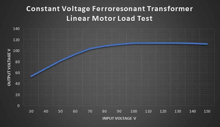
CVT Linear Motor Load Test
4) Load test- Non-Linear Load
The CVT is connected to a nonlinear load to check its performance when non- sinusoidal current is drawn. For this application, CFL lamp is chosen. The wattage of CFL lamp is 13W and the CVT is rated for 60VA.
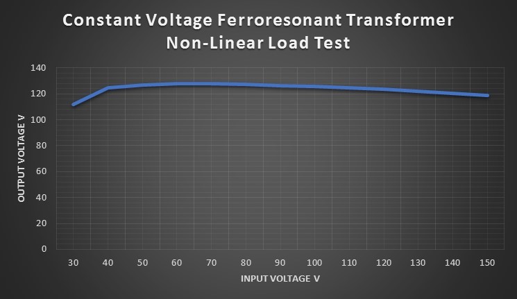
CVT Non-Linear Load Test
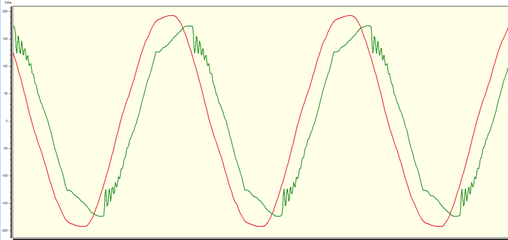
It is noticed that when the Ferroresonant transformer is feeding non-linear loads, an oscillation on the voltage waveform is seen at the peak of the output voltage waveform. In this particular test, the oscillation was around 5Khz frequency. The output voltage and the output load current waveforms are shown below.
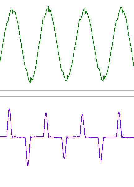
CVT voltage oscillations
Here is a close up of the oscillation on the voltage waveform.
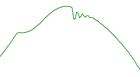
CVT voltage oscillations
This oscillation is due to the interaction between the Ferroresonant capacitor and the system inductance. When the non-linear load is increased the oscillations become more pronounced as shown below. All large servers and other computer power supplies use Power Factor Corrected power supplies which present a negative input resistance over some frequency range. This when coupled with the relatively high and resonant impedance of the Ferro transformer can give rise to spontaneous and damaging oscillations as seen in the graphs below.
These oscillations at the peak of the CVT output voltage can negatively affect the computer power supplies and other non-linear loads. This is part of the reason that it is recommended to oversize the CVT when powering electronic power supplies. CVT are usually sized larger than the VA rating of the load sometimes up to twice larger than the load VA. Care should be taken while applying CVT with large electronic loads.
CVT voltage oscillations
Note that some manufacturers of Ferroresonant transformers (CVT) recommend to not use them with modern switched mode power supplies.
Below is the summary of all the load test on this specific CVT.
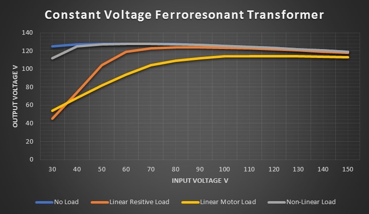
CVT Regulation Tests
Transient Voltage Suppression
To test the attenuation of line generated transients a high frequency transient is introduced on the primary and its corresponding response is measured on the secondary side. It is noticed that the transient at the secondary side is attenuated almost 33dB, a very large amount of attenuation.
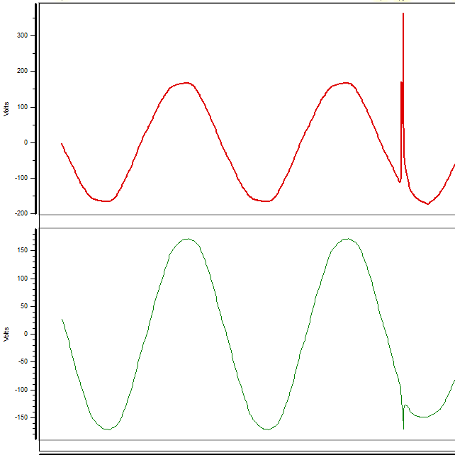
CVT Transient Suppression, Transient attenuation: Input waveform on top and output from ferro on the bottom.