What is a Line Reactor?
Line reactor as used in VFD/VSD application is an inductive component used at the line side or supply side for harmonics mitigation, voltage buffering, reduce commutation notches, reduction of differential mode noise etc.
Line Reactors are specified based on the current rating (Amps) and the inductance (mH). Current rating is based on the drive full load rating, while the inductance is expressed in milli-henry (mH) or more commonly expressed as %Z, % impedance or Uk. This %Z or %impedance convention is derived from the practice used with the transformers. %impedance of the line reactor is the percentage of the drive impedance at full load.
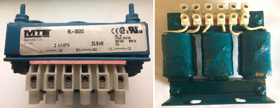
Line Reactor
A 3% line reactor is usually sufficient for most applications. A 5% line reactor can be used in situations with extreme harmonics problems. Note that adding reactors greater than 5% gives very less additional benefit and the cost would outweigh the incremental increase in performance. This is usually the case with low voltage drives. For medium voltage drives, this usually does not apply and typically require impedance greater than 5%.
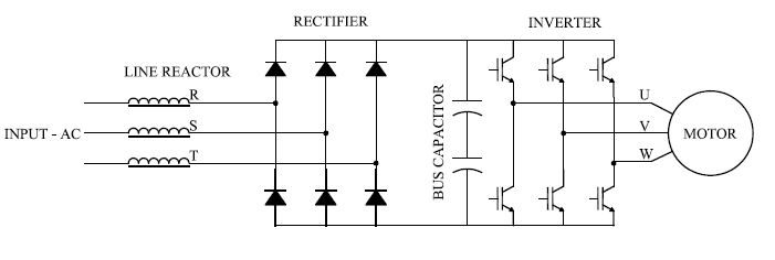
Line Reactor on VFD
Calculating Line Reactor Impedance
The formula for calculating the % impedance of a line reactor is as follows:
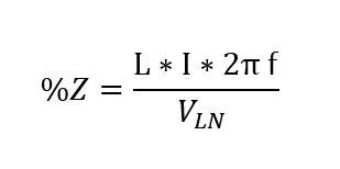
Line Reactor %Z Equation
Where,
%Z= impedance offered to the drive at the current I
I= drive current
f= system frequency (50/60Hz)
L= Inductance of the reactor (usually expresses in milli-henrys)
V_LN= Line-Neutral voltage at the input to the drive. Even for a delta (ungrounded) system use the calculated line-neutral voltage.
Note that the ‘effective’ %Z or % impedance depends on the current drawn by the VFD. This means say we size a reactor for the full load rating of the drive, and the drive only operates at 25% of the rated HP all the time, then effective impedance offered to the drive on the supply side is also 25% of the original rating. Most often this is not a problem since operating at a lower rating would inject lower magnitude harmonic current as a percentage of the full load current. If a tighter harmonic control is desired then line reactor may have to be sized based on the actual load current.
Use the calculator below to obtain the inductance required for a desired line reactor impedance. The calculator can also be used to estimate the effective impedance when the drive is operated at a lower rating than the design rating.
If conversion from a known inductance to % impedance use calculator below:
AC Voltage drop
Line Reactor create a voltage drop due to the very nature of an inductor, i.e. it will resist the sudden change of current. However, it should be noted that the fundamental (50/60Hz) voltage drop across the Line reactor will be a small value. The reason for this is that drives are inherently high displacement power factor devices (Fundamental frequency power factor). As such the fundamental frequency voltage drop across the reactor will be very less. The 50/60Hz fundamental frequency voltage drop across a reactor can be estimated using the calculator below.
Voltage drop for harmonic components will be higher since the harmonic currents will typically have poor power factor. The plot below shows the voltage drop across line reactor for one phase when feeding a VFD. Note that the voltage drop is not sinusoidal and has strong presence of harmonic components. Also noted here from visual inspection that the 60Hz voltage drop across the reactor is almost non-existent.
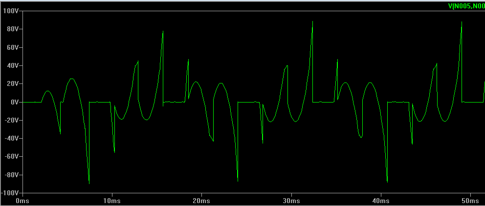
Harmonic Voltage Drop Across Line Reactor
DC Bus Voltage Drop
The addition of line reactor will result in a slight reduction of DC bus voltage. However, the relationship is not linear. For example if the DC bus voltage of a drive with 3% line reactor is 633V, changing the reactor to 5% will not result in 5% drop in voltage. This will only drop the voltage by roughly (5%-3%)/2 = 1%. In this case the DC bus voltage will be 626V with 5% line reactor vs 633V for 3% line reactor.
The chart below shows the simulated DC bus voltage of a 480V VFD with line reactor varied between 1% and 5%. Actual DC voltage will depend on the motor load, supply voltage and supply voltage power quality.
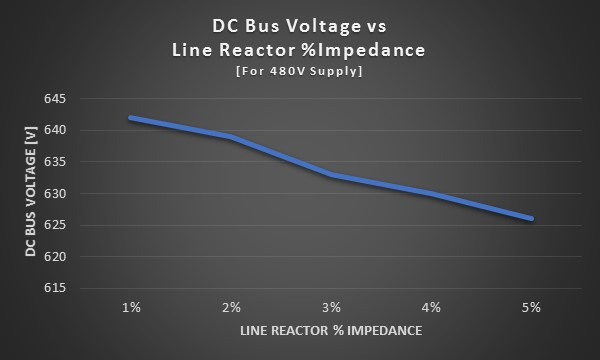
DC Bus Voltage vs Line Reactor % Impedance
Advantages of having Line Reactor
Line Reactor Current Harmonic Attenuation
- Helps reduce current harmonics at the input side of the drive. This will have a positive effect on reducing the facility voltage distortion levels as well as helps in meeting the local harmonic emission requirements.
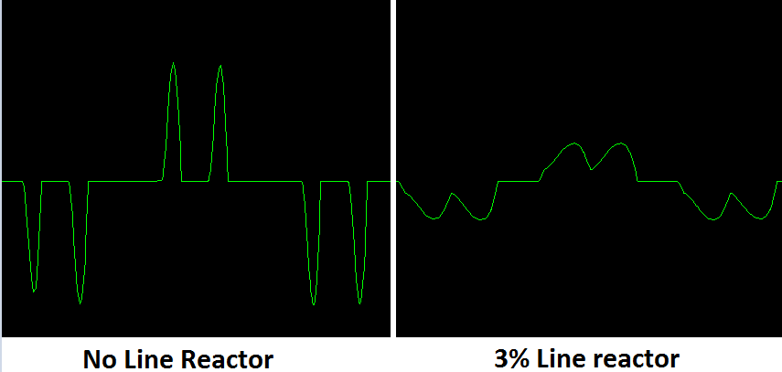
- Installations where the drive is installed close to a supply transformer with much higher KVA rating, adding a line reactor can protect the front end diodes and DC bus capacitors from very high short circuit currents. These high magnitude currents occurs 6 times in a waveform cycle and can shorten the life of bus capacitors. From the above figure it can be observed that when there is no line reactor, the DC current pulse in to the bus capacitor is high and narrow compared to the case with the line reactor. These sharp pulses of current at high magnitude can create additional heating in the capacitors and shorten the life.
- Voltage sags that occurs during a drive running condition typically results inrush current immediately on recovering the voltage. This surge of current can damage the front end electronics especially if voltage sag occurs within close time span. A line reactor would reduce the magnitude of the surge current and hence protect the drive front end electronics.
- Help with controlling differential mode noise from the drive.
- DC drives that have front end Silicon Controlled Rectifiers (SCR) create voltage notching on the AC input side. This is due to a process where one SCR turns on while the other is in the process of turning off- a process known as commutation. During this brief time, a short circuit between two phases is created which results in a voltage notch. A line reactor is typically used in front of the SCR based drive to reduce the notch depth. Though adding line reactor results in reducing the ‘depth’ of the voltage notch, it will increase the ‘width’ of the notch. In most cases increase in ‘width’ of notch is not a problem, but something to keep in mind.
- Reduce the possibility of drive tripping on over voltage during a electric utility capacitor switching. Note that if the drive is idling a line reactor may not be able to prevent over voltage shutdown during capacitor bank switching.
- Having line reactors on all the variable frequency drives is usually a ‘must have’ if the facility plans to install any kind of ‘Active Harmonic filter’ for harmonic control in the electric system. Active harmonic filters usually require at least a minimum of 3% reactance at all the drives in the electric service that it is intended to be applied.
What does Line Reactor at the input side the VFD not do?
- Protect the motor from the switching voltage of the VFD (Long lead effects, dv/dt effects)
- Protect the motor bearing from damage
- Reduce audible motor noise
- Reduce motor temperature
- Provide common mode noise attenuation originating at either the input or output side
- Provide ground reference for the drive
- Provide any kind of voltage change
If any of these is desired then consider installing a motor output reactor, output filter or a sinus filter. For controlling reflection of voltage and potential damage to motor / cable consider using a motor termination network. If it is desired to provide ground reference for the drive or have a voltage change, then consider installing a drive isolation transformer.
Line Reactor for single phase drives
Line reactors are typically available as three phase units. Three phase line reactors can be used for single phase drives. This is done by connecting the two input phases to the outside coils of the three-phase reactor leaving the center coil unconnected.
It should be noted that the total reactance on the supply side is now two times the reactance of the line reactor. This should be noted when applying three phase reactors along with single phase drives.
Common mistakes made when installing Line Reactors
- Installing line reactor when there is already a DC link choke built in to the drive: While this should not cause issues with drive performance, it is unnecessary.
- Installing line reactor along with isolation transformer on the supply side: This is unnecessary and costly. Either reactor or isolation transformer should be sized to provide the required impedance to the drive. Adding too much impedance on the supply side of the drive could lead to reduced DC bus (reservoir) voltage and consequent under voltage issues.
- Installing line reactor with a tuned harmonic filter. Many tuned harmonic filters have a line side reactor as standard before the filter capacitor and hence adding additional line reactor is unnecessary.
- Adding line reactor when the supply source is very weak: This could occur when the drive is fed by a small local generator which has high source reactance. The high source reactance along with the reactance of the line reactor could lead to significant DC voltage reduction and hence under voltage tripping.
- Not sizing the Line reactor for the drive rated HP: As mentioned in the section above, the effective impedance of line reactor depends on the current that is flowing in the circuit. If the reactor is oversized for the drive then it will not offer required impedance for harmonic control.
Also Read: DC Choke, Isolation Transformers, Line Reactor vs Isolation Transformers