A DC choke (DC Link Choke) is used between the rectifier section and the bus capacitor section of a variable frequency drive.
Advantages of DC Choke for VFD
DC choke offers many benefits some of which are:
- Controlling line side harmonics by limiting the peak value of the line current.
- Reduces the ripple in DC bus voltage, there by helping reduce the heat loss in the bus capacitor and prolong its life.
- Reduced AC voltage drop compared to line reactor.
- Reducing the transient switching current magnitude in to the DC capacitor after a voltage sag (dip) event.
Position of DC Link Choke
If specified, DC choke will be built in to the drive and for large drives there will be slots available to install DC choke if customer decides to install it in future. Below is a brief description of the advantages of DC link choke.
1) Reducing line side harmonics:
DC choke behave similarly to AC line reactors from a harmonic mitigating standpoint. They both help reduce the peak value of the drive input current.
Note the waveform below for a drive with and without a DC choke. The first is a drive connected directly to the AC power supply and the second is the same drive having a DC choke installed on the DC bus.
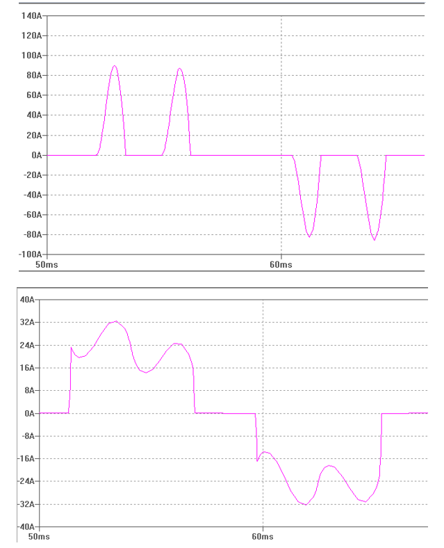
Drive Input current waveform without and with a DC Choke
Half of the required inductance is installed on the positive bus and the other half is installed on the negative bus. The inductance can also be lumped together at either positive or negative bus if required.
DC choke attenuates 5th and 7th harmonics better than AC line reactors. Considering the fact that 5th and 7th are by far the largest harmonic contributors, this will lead to reduction in total current harmonic distortion. Theoretical current harmonic distortion level with DC choke is 32% and with AC line reactor this is 37%.
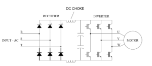
Drive schematic showing DC Choke
Notice that the input current waveform with DC choke has a characteristic shape. A sharp rise in current followed by flattening. This is different from input current waveform for a line reactor. See the waveform above. This characteristic waveform can be used to quickly identify if a drive has input line reactor or a DC choke.
2) Reducing DC Bus Ripple
Without a DC choke, we can expect a +/-5% DC voltage ripple on the DC bus. By adding a DC choke, the ripple will be reduced to +/-1.5% or smaller. Smaller ripple will result in lower heat losses in the bus capacitor and hence longer life. There is usually a slight reduction in DC bus voltage with the addition of DC choke, which can be considered minor considering the other potential benefits.
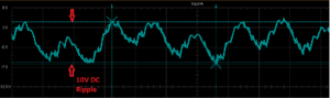
DC Bus Ripple measured on a 1HP, 240V AC Drive
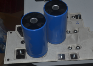
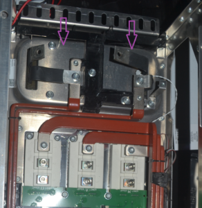
Bus Capacitor shown removed from Drive. The bottom plate is low inductance capacitor busbar.
3) Voltage Drop
The voltage drop of an AC line reactor is higher than that of a DC reactor with similar % impedance. DC choke reduce the ripple voltage and do not have much effect on the overall DC bus voltage. This is because the impedance offered by a reactor to a DC current is zero since the frequency is zero (Z=j2𝝅fL). A limited reactance is only offered when there is a transition of current from on state to off state or vice versa. Voltage drop is usually minor around 1% of the system voltage. This means having a DC choke will result in a slight improvement in drive output voltage compared to a AC line reactor.
4) Surge Current Protection
During a voltage sag (voltage dip) under drive running condition, the DC reservoir (DC bus) voltage could drop to very low levels. Upon restoration of voltage, a sudden surge of current to recharge the DC bus capacitor can be observed. This surge of current could be 5-10 times the rated peak current of the drive and may damage the front-end diodes. Even in drives with pre-charge circuits, this is a problem since the pre-charge circuit will not be effective during momentary voltage sags. DC choke will reduce the peak current magnitude upon restoration of voltage after a voltage sag.
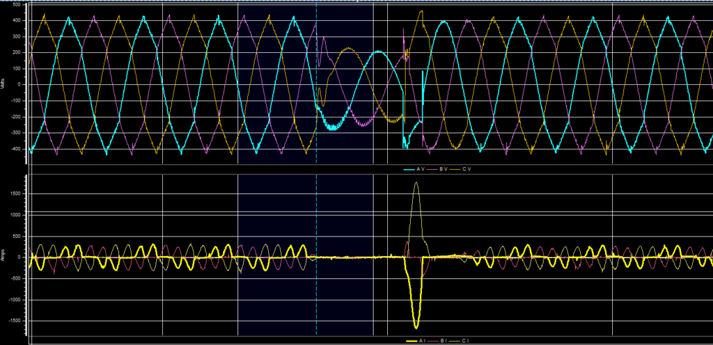
A sharp current surge is seen after the voltage sag (voltage dip) event. Current peak is 6X normal peak. Top graph is voltage and bottom is current.
Disadvantages of DC Choke:
- Adding a DC choke (DC reactor) to the drive will increase the weight and physical dimension of the drive.
- In systems with low short circuit levels, there is a slight possibility of creating an oscillating circuit due to the interaction between line inductance, DC choke and the bus capacitors. This reduces the performance of the drive and could even shut down the drive on over or undervoltage. If found, these oscillations can usually be mitigated by drive settings adjustment in the drive software.
- The inductance of DC choke has to be approximately twice larger than AC line reactors to get the same performance.
- DC choke do not provide protection to the diode front end of the drive from voltage transients on the AC supply voltage. Due to this reason, additional input transient voltage protection to the drive must be provided. These could be in the form of surge suppressors, MOV etc.
Sizing a DC Choke
The following are the key electrical parameters involved in selecting the right DC choke:
- Reactor relative impedance (%)
- DC amps
- Inductance (mH)
- Ripple frequency (Hz)
- Maximum voltage (V)
There are also other parameters to be considered like the ambient operating temperature as well as the insulation class of the DC Choke winding.
1) Reactive relative impedance: This is also known as short circuit impedance. Generally, you would need almost twice the inductance of an AC line reactor at the DC bus to obtain equivalent performance. So if 3% ac reactor is sufficient for AC line reactor then as a rough estimate you would need 6% impedance reactor on the DC bus. The DC choke reactor can be installed 3% on the positive bus and 3% on the negative bus. This is because the inductance on the positive and negative bus is additive.
Other way to obtain this information would be to contact the manufacturer of the drive.
2) DC Amps: The rated current of the DC choke can be approximated by calculating the average DC bus current. Use the calculator below to calculate the average DC bus current for a given KW of motor load.
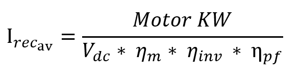
Where,
Vdc= DC bus voltage which can be estimated to be 1.35* RMS AC voltage.
I_recav= Average DC output current of drive rectifier
𝝶m=Efficiency of motor
𝝶inv= Efficiency of inverter
𝝶pf= Power factor of inverter
3) Inductance: The required value of inductance needed to obtain the impedance needed for harmonic control need to be calculated. Approximate value of inductance can be calculated using:
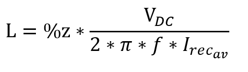
Where,
%z= % impedance required from the DC choke
VDC= Drive DC bus voltage which can be calculated as 1.35 * AC RMS Voltage
f= system frequency
I_recav= DC output current of drive rectifier
L= Required Inductance in milli Henry (mH) to be installed at both positive and negative bus.
4) Ripple frequency: Select six times the system operating frequency for this parameter. For 60Hz systems, use 360Hz and for 50Hz use 300Hz. If we measure the ripple frequency on the DC bus, we will get 360HZ ripple for 60Hz and 300Hz for 50Hz system. This is the origin of this ‘ripple frequency’ parameter in the DC choke selection.
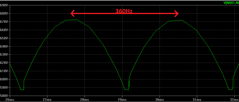
DC bus voltage showing the ripple frequency for a 60Hz system
5) Maximum voltage: Maximum voltage of the DC choke is selected based on the AC input voltage of the drive. A quick rule to estimate the maximum possible DC voltage is to multiply the rms AC voltage by square root of 2, which is 1.414. For 415V AC input systems, it can be calculated that the maximum DC bus voltage is 1.414 *415V= 586.8V DC. For low voltage drives, it is very common to use 600V, 800V or 1000V rated DC chokes.
Also see Isolation Transformers and Line Reactors for VFD applications.