A power cable could appear as a simple electrical device, a conductor wrapped in an insulation. However, as you can find in this article, an electrical cable is a well thought out piece of engineering that has to withstand enormous stress over its life time. It is important for power system engineers to know more about cable construction to make intelligent engineering designs.
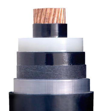
Here is a picture of a 15kV class Medium Voltage Cable (High Voltage Cable) with the outer jacket removed.
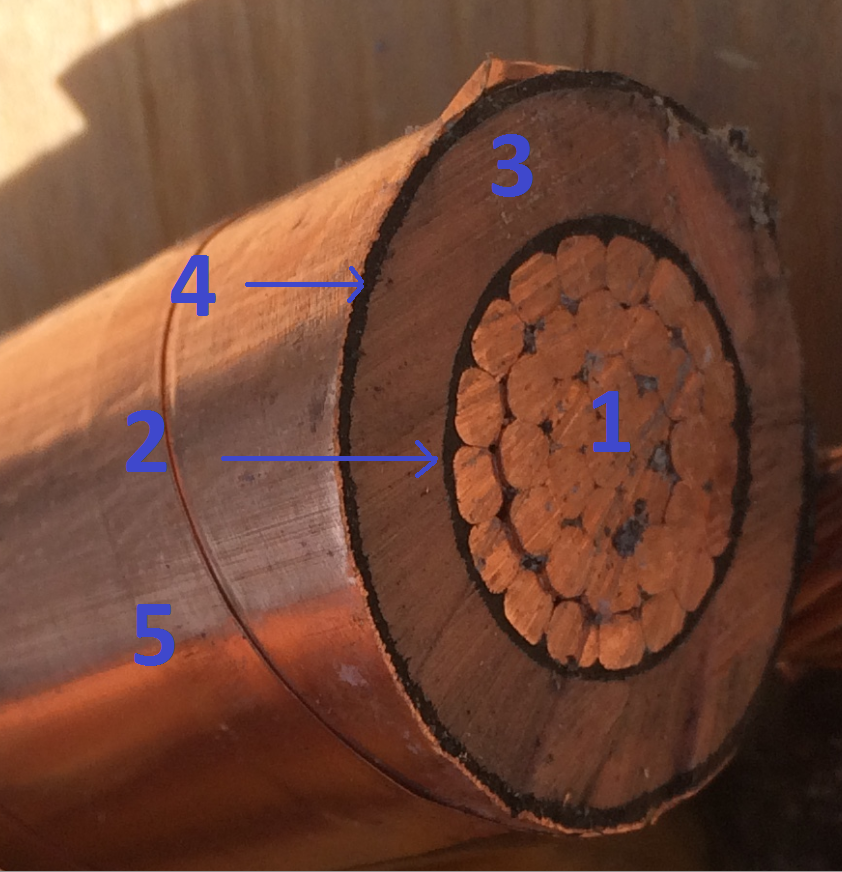
15kv cable with outer jacket removed
The various layers of the cable from inside out are:
-
Conductor
-
Conductor Shield
-
Insulation
-
Insulation Shield
-
Outer Shield
-
Outer Jacket (Not shown in the picture)
1) Conductor: The conductor carrying current could be copper or Aluminum and the diameter of the cable varies by the load that the cable is designed to carry. The conductor itself could be of many different types:
-
Solid
-
Stranded Concentric Round
-
Stranded Compressed Round
-
Stranded Compact Round
-
Stranded Compact Sector
Stranded Compact Concentric Round is found to be commonly used for larger diameter cables whereas for very small diameters, solid conductor is commonly used.
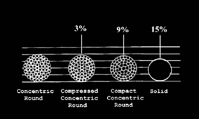
Comparative sizes and shapes of stranded and solid conductors
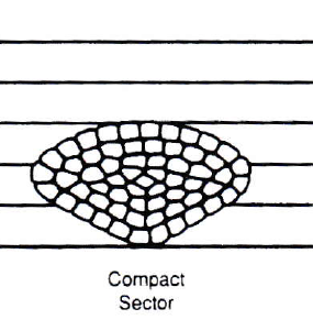
Compact Sector
The benefits of stranded conductor is that it offers improved flexibility. For similar ampacity, a solid conductor will have smaller diameter compared to a stranded conductor.
2) Conductor Shield: Conductor (Strand) shield is usually a semiconducting material applied over the outer edge of the conductor to ‘smooth out’ the conductor contours. Application of semiconducting conductor shield helps remove any isolated ‘air pockets’ that could lead to corona and failure of the cable in the long run. Additionally, application of conductor shield results in a smooth conductor surface over which insulation can be installed. Semiconducting shields evens out the electric field at the interface between the conductor and insulation and hence reduces the electric field gradient at this interface. Without the semiconducting layer high concentration of electric field at the interface could break down the insulation.
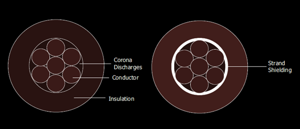
Conductor Shield
It should be noted here that the term ‘semiconducting material’ does not refer to silicon based semiconductors. Rather the semiconducting material refers to material that is ‘somewhat conducting’. These are made by adding carbon to insulation materials like PE or XLPE. See a closeup picture of semiconducting insulating layer towards the end of this article.
3) Insulation: Insulation used for cable construction can be broadly classified as thermoplastic or thermoset.
Thermoplastic material loses their form upon subsequent heating, while thermoset material tends to retain their form. This is because, once the wire is extruded on to wire, it undergoes a chemical change known as vulcanization, cross-linking or curing. These processes fix the physical property such that subsequent heating will not cause it to melt, flow or drip.
Example of thermoplastic material is PVC and thermoset example is XLPE insulation and EPR. There are also variants of these insulation systems in the market. Tree retardant XLPE is one such example.
Some of the popular insulations are listed below:
-
Polyethylene
-
Cross-linked polyethylene (XLPE)
-
Ethylene-Propylene Rubber (EPR)
In the earlier part of 20th century paper insulated cables (PILC) were common before the advent of polymer-insulated cables. Some of those original cables are still in use! These are known as PILC cables, which stands for Paper Insulated Lead Covered are not very common currently. They are required sometimes where it is necessary to splice in to existing PILC cables system and some manufacturers do still offer them.
Some of the additional parameters important in the selection of cables are:
-
Dielectric Constant: Determines the capacitance of the cable.
-
Volume Resistivity: Determines the current leakage through the insulation.
-
Dielectric Losses: Losses due to dipole movements inside the cable.
-
Dissipation Factor: Ratio of resistive to capacitive current drawn by cable. This is also known as loss angle, loss tangent.
Additional consideration on selecting insulation is the ground fault clearing time, based on which 100%, 133% or 173% insulation may be selected.
100% Insulation: Applications in which ground faults will be cleared in less than 1 minute.
133% Insulation: Applications in which ground faults will be cleared in less than 1 hour.
173% Insulation: Applications in which ground faults clearing time is infinite. This usually is used in industries where orderly shutdown of equipment is necessary to protect equipment or personnel. The shutdown process could take an indefinite amount of time and hence the insulation will be subjected to additional stress over a long period of time.
The selection of 100%, 133% or 173% insulation will progressively result in larger diameter cable for a given conductor size. 133% insulation is often preferred insulation system for 15kV and above voltages even for systems with ground fault protection that could clear in less than a minute. Probably this is done as an assurance or designing on the conservative side.
4) Insulation Shield: This is a semiconducting nonmetallic material over the dielectric circumference. The material should be capable of conducting leakage current from the conductor through the insulation to the outer shield (current due to capacitive charging etc.) without appreciable voltage drop. Insulation shield also provides a smooth surface over which metallic outer shield can be installed with good low resistance connection. Semiconducting shield evens out the electric field at the interface between the insulation and outer shield or neutral and hence reduces the electric field gradient at this interface. Without the semiconducting layer high concentration of electric field at the interface could break down the insulation.
It should be noted here that the term ‘semiconducting material’ does not refer to silicon based semiconductors. Rather the semiconducting material refers to material that is ‘somewhat conducting’. These are made by adding carbon to insulation materials like PE or XLPE.
5) Outer Shield: This is a metallic wire or tape covering over the insulation shield. The outer shield will carry the capacitive leakage current and sometimes the fault current itself to the ground. Grounding the shield also results in symmetrical electric field distribution within the insulation resulting in better stress distribution. By grounding the outer metallic shield (which could be tape or wire) the potential of the outer surface of the cable is referenced to ground. This will prevent any dangerous touch voltage accumulating on the high voltage cable.
A concentric neutral cable is produced using a would wire over the insulation in lieu of a tape shield. The wire would offer all the benefits of a shield plus it will be rated to carry the neutral current. Additional discussion on concentric cable is at the end of this article.
It should be noted that there are two methods of grounding the outer shield:
-
Single Point Grounded System
-
Multiple Point Grounded System
-
Cross Bonded Grounded System
Each arrangement has its advantages and disadvantages.
6) Outer Jacket: Outer jacket is used to provide environmental and mechanical protection to cable. It could also be used for enhancing the flame resistance of cable as well as improved sunlight resistance. Outer jacket could additionally be colored to aid in easy identification in the field.
Shielded or Non-Shielded Medium Voltage Cable?
Per the National Electric Code 2011, 310.10(E) Non-shielded, ozone resistant insulated conductors with a maximum phase-to-phase voltage of 5,000V is permitted in Type MC (Metal Clad) cables in industrial establishments where only qualified persons service the installation. For other establishments, solid dielectric insulated conductors operated above 2,000V in permanent installations shall have ozone-resistant insulation and shall be shielded.
Cross Section of High Voltage Cable
The purpose of shield as mentioned in section 5 above is to have the electric field stress evenly distributed within the insulation. When a conductor in a cable is energized, electric field originates from the conductor to the grounded surface. For an unshielded cable touching a grounded surface at one point, the electric field will be ‘crowded’ at the interface between the conductor and the ground. Or stated otherwise, the insulation will be stressed more between the conductor and the ground.
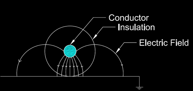
Electric field overstress on insulation due to unshielded power cable touching a grounded surface.
In a shielded cable, the shield is typically grounded. The electric field lines originate at the conductor and will spread out evenly from the conductor through the insulation to the shield ground. The electric field stress is hence distributed ‘evenly’ around the circumference of the cable rather than ‘crowded’ in the case of non-shielded cable. This will reduce electric field stress on the cable and helps prolong its life.
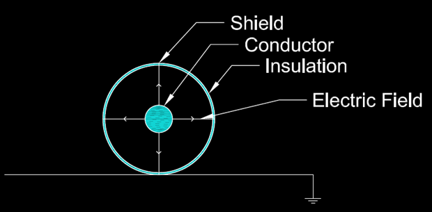
Electric field is evenly distributed within insulation for shielded power cable touching a grounded surface. The shield itself will be grounded.
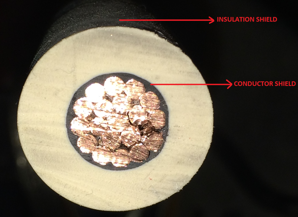
15kV cable with conductor shield and insulation shield (outer shield and jacket are removed)
Terminating the shielded power cable requires special consideration and is not straightforward as terminating non-shielded cable. At the point of termination, the outer shield will have to be stripped back and this will cause insulation to be over stressed at the termination due to electric field that becomes ‘crowded’ at the interface. Suitable stress relieving termination (Stress cones) will have to be applied at the termination to avoid premature cable failure.
Concentric Neutral Cables
Concentric neutral cables use the outer shield of the cable as the neutral current return path, while also functioning as the insulation shield. The shield (neutral) in this case has to be sized to conduct the expected neutral current.
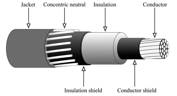
Concentric Neutral Cable [1]
The neutral is usually wound helically around the insulation shield and is expected to carry the full neutral return current. For single phase utility cables, the neutrals are usually full size meaning the cross section of the helically wound neutral is the same as the center phase conductor.
Concentric neutral cables are extensively used in utility residential feeder applications- majority with full neutral wires and also for feeding commercial and industrial customers though to a limited extent.
As the outer jacket deteriorates, the neutral wires could come in contact with earth and this has been one of the reasons behind stray voltage issues encountered in many areas using underground concentric neutral cables.
References: [1] Electric Power Distribution Handbook , T.A. Short