Isolation transformers are used in drive (VFD / VSD) as well as many other applications to provide any of the following:
-
Voltage change: Isolation transformers can be used to supply a VFD that has a different input voltage from the system voltage. This could be useful especially when drives are purchased from overseas location that may have a different voltage rating.
-
Provide a stable line to ground voltage reference: Isolation transformers that have wye-grounded secondary can provide stable line to ground voltage to the drive. Some drives ‘require’ a grounded source to work properly and most drives in the market today will require some minor adjustment to the front-end noise filter circuit if applied in an ungrounded source supply.
-
Ground current control: By having a wye-grounded secondary isolation transformer, the ground currents originating at the VFD/motor (due to IGBT switching, stray capacitance etc.) have a well-defined path back to the source which is the secondary of the isolation transformer. (remember the isolation transformer is a separately derived source and hence ground current will have to return to the secondary neutral of the transformer)
-
Common mode noise control: Isolation transformer prevents transfer of common mode voltage from primary to secondary as well as from secondary to primary. This could help with issues related to data communication error due to presence of common mode voltage. Common mode noise is discussed again at the end of this article.
-
Provide required supply side impedance to the VFD for harmonic current control: Drives need a certain impedance on the supply side (input side) for harmonic control as well to prevent damage to drive from high short circuit currents. Isolation transformer provides the required impedance by virtue of its leakage reactance. Note here that the ‘effective’ impedance provided by the transformer will also depend on the rating of the transformer vs the rating of the drive. Use the calculator provided in this article to calculate the effective impedance of the isolation transformer at the rated drive load.
-
Mitigate voltage notching (for DC drives and drives with SCR front end) [See Voltage Notching for more information]. Isolation transformer provides the required supply side impedance required for controlling voltage notching.
-
Transient noise attenuation originating at the supply side. Isolation transformers are effective in attenuating transients originating on the supply side from affecting the drive.
-
Isolate drive from system voltage transient events: Isolation transformers provide protection from system generated voltage transients such as capacitor switching which in the absence of isolation transformer could cause an over voltage shutdown of VFD.
-
Harmonic Current Cancellation: For similar sized VFD, by using a combination of delta-wye and delta-delta transformers to feed two identical drives, the harmonic currents at the primary side of both transformers get some cancellation. This is due to the 30-degree phase angle shift when passing through delta-wye transformer. The current flowing through delta-delta will not experience any phase shift. If used wisely this design can lower the effective harmonic current at the service entrance location. Note that delta-delta transformer will not be able to provide a ground reference to the VFD.
Isolation transformers provide all the functions listed above and is often the preferred method to provide the required impedance for large drives. While line reactor provides many of the benefits of isolation transformer in a drive application, there are some key differences as well.
Drive Isolation Transformer Sizing
Drive isolation transformer can be selected by consulting with the drive manufacturer. If this is not possible, then the below chart can be used to as a guide to select the transformer kVA based on the drive rated horse power.
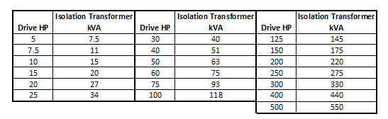
VFD isolation transformer sizing
Drive Isolation Transformer Impedance
Usually the impedance of the drive isolation transformer is between 4-6% and this value will vary between the drives and the application. A higher impedance may be required for any of the following cases:
-
Drive is applied close to the service entrance with high short circuit capability
-
The manufacturer of the drive asks for a higher minimum impedance
-
Additional harmonic control is desired
Often times a transformer is selected which could have a higher kVA than the rating of the drive. If the drive has a certain minimum required impedance then it becomes a question whether this ‘oversized’ isolation transformer is providing the required line impedance. Use the calculator below to find the effective impedance offered by the isolation transformer at the actual drive rating.
As you can observe from the above calculator, a transformer that is oversized for a particular drive may not offer the required line reactance required by the drive.
Shielded Isolation Transformer or Unshielded Isolation Transformer?
Some manufacturers suggest and recommend ‘shielded’ transformer for better noise control. What is a shielded isolation transformer?
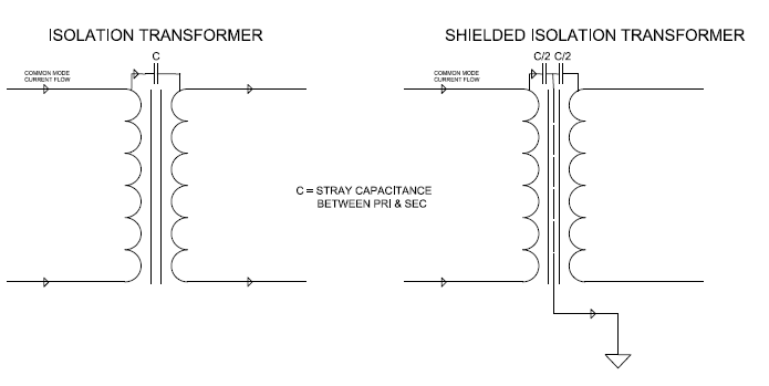
A shielded isolation transformer has an additional conducting foil of nonmagnetic material (copper or aluminum) sandwiched between the primary and secondary coils. The foil essentially splits the primary to secondary winding capacitance in to two and the foil should be grounded at one point to the system ground.
There are two main types of noise disturbance in power system, Common Mode Noise and Differential Mode Noise. Isolation transformers even without shielding provide some common mode noise attenuation. Shielded isolation transformer offers additional common mode noise attenuation depending the transformer secondary grounding connection. Isolation transformers do not offer differential mode noise attenuation. The usefulness of shielded vs unshielded transformer depends on whether the secondary circuit is grounded or not which is an often overlooked factor. The effect of secondary grounding is discussed below.
Transformer with Ungrounded Secondary: Shielded isolation transformers can prevent transfer of common mode noise from primary to secondary when the secondary of isolation transformer is ungrounded. Common mode currents are essentially zero sequence currents flowing in the primary circuit towards the isolation transformer. If the transformer has a delta primary then the currents would circulate in the delta windings and similar currents would be induced in the secondary delta windings. In this case, having an electrostatic shield would provide attenuation to common mode current.
Transformer with Grounded Secondary: If secondary is grounded (which is very common), then common mode energy cannot be transferred to the secondary side. Common mode currents are essentially zero sequence currents flowing in the primary circuit towards the isolation transformer. If the transformer has a delta primary then the currents would circulate in the delta windings and no current would flow in the secondary wye-grounded circuit. Using sequence components terminology this is can be stated that the zero-sequence circuit of the delta-wye-grounded transformer is open. Hence if the isolation transformer secondary side is grounded wye then having a shielded isolation transformer provided no additional benefits.
Below is a short description of the common mode and differential mode noise with respect to isolation transformers.
Common Mode Noise: All transformers have a primary to secondary ‘stray’ capacitance that could couple common mode noise from the primary side to the secondary side. Remember that the common mode signal is the signal that is common to all three phases (in a three-phase system) with respect to ground. In single phase systems this noise would be common between line and neutral with reference to ground. This common mode signal travels from the primary to the secondary through the interwinding stray capacitance. The return path for this common mode current will be through the line to ground capacitance of the load.
Drive Isolation Transformer
The above picture shows a regular isolation transformer and the ‘parasitic stray capacitance’ between the primary and secondary winding. As can be seen the common mode noise is easily transferred across the winding through this stray capacitance.
From the second picture o the right, It can be observed that adding the metallic foil would split the capacitance in half. Since the center point of the capacitance is grounded, the signal that is common to all phases with respect to ground (common mode noise) will find a path back to source through the foil capacitor and not through the load.
Differential Mode Noise: Differential mode noise is the noise that appears across the phase and neutral/ground conductor. The flow of differential mode current is from the phase conductor through the load and return back to the neutral/ground conductor. The current flow in phase and neutral/ground conductor is in opposite direction. This is different as opposed to common mode noise wherein the current flows in all phase conductors in the same direction and then return through the ground circuit.
Differential noise is less affected by the presence of isolation transformer since the coupling mechanism across the winding is magnetic as opposed to electrostatic (capacitive) in case of common mode noise. Additional techniques, like surge protection, line filters etc. should be added to mitigate differential mode noise.
Additional reading: Line Reactor, Isolation Transformer, DC Choke.