Drive (VFD) overvoltage protection for common low HP drives is based on the measured voltage on the DC bus of the unit and not the input AC voltage. It is important to realize this fact to aid in troubleshooting. Any and all events that could cause a jump in DC bus voltage could lead to a dc link overvoltage fault event. This guide will help you in troubleshooting VFD problems with overvoltage fault code.
Note: Overvoltage protection for drives is turned on the moment drive is powered ON. It does not matter if the drive is running or not.
Also read- How to measure DC bus voltage and DC bus voltage ripple
For large HP drives, medium voltage (high voltage) drives, there could be overvoltage fault protection on the input, DC bus and on the output side. In these cases, it is important to know where the voltage signal is derived from for overvoltage fault code troubleshooting.
The ideal DC bus voltage for a 3 phase VFD under idle (not running) condition should be approximately square root of 2 multiplied by the AC RMS voltage. Hence for a 480V, 3 phase system the expected idle DC bus voltage should be around 678V. For a 415V 3 phase system drive idle DC bus voltage should be around 586V. The actual value of DC bus voltage is dependent on many parameters some of which are:
- AC input voltage peak voltage
- Load on the drive
- Presence of AC Line Reactors
- Presence of DC Choke
- Presence of Isolation Transformers
Due to the above factors, DC bus voltage under normal condition could vary a lot. Typical nominal values are:
- 230V System: 310 VDC
- 415V System: 560 VDC
- 480V System: 648 VDC
- 600V System: 810 VDC
Measuring DC bus voltage require knowledge of the expected DC voltage magnitude and equipment rated to withstand that voltage. Most drive data sheet will provide magnitude of the DC bus voltage on the HMI screen or this can be measured at terminals on the drive suggested by manufacturer.
The overvoltage threshold at which fault is triggered will vary between manufacturers. Here are few manufactures overvoltage fault thresholds:
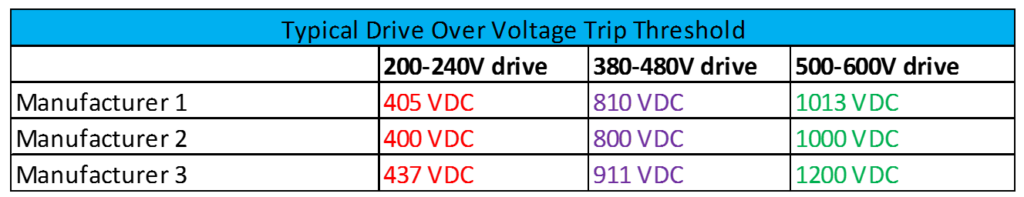
Typical VFD Overvoltage Trip Threshold
Comparing Overvoltage trip thresholds with the nominal DC bus voltage we can see that the overvoltage trip settings for most drives is 130-150% of nominal DC bus voltage. Corresponding AC voltage at which overvoltage fault occurs can be calculated by dividing the above values by 1.35.
Typical Reasons for having an Overvoltage Fault on VFD
- Regenerative feedback
- Induced voltage
- Power factor correction capacitor switching
- Input voltage with very high crest factor (Form factor or Peak factor)
- Low level system resonance
These possibilities are discussed in detail below.
- Regenerative Feedback
If the drive is supplying current to a motor with a lot of inertia then the motor could act as a generator feeding voltage back to the drive during periods of deceleration. This is called regenerative feedback. This can also occur if the motor is a PM (Permanent Magnet) type motor. Another possibility for regen is when the load is already running when the drive is trying to start it.
Solution:
- Increase deceleration time.
- Program the drive to stop the motor. In this method the drive would coast the motor to stop in a predetermined deceleration ramp fashion.
- DC injection braking: For applications that require a fast stopping time, the drive can be programmed to ‘inject’ DC voltage in to the motor windings for predetermined time to brake the motor. Check with the drive manual if this option is available.
- Dynamic braking (DB): If the drive has a dynamic breaking option available, then an internal transistor will be switched ON to dissipate the excess energy on to an externally mounted braking resistor ‘R’.
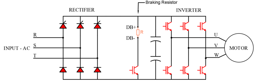
Drive schematic with location of dynamic braking resistor
The dynamic braking circuit will monitor the DC bus voltage and would trigger the transistor to be tuned ON in the event it senses a regenerative overvoltage condition. The value at which the DB transistor will be turned on is approximately 5% below the overvoltage fault threshold. For example, for a 460V drive the DB resistor is switched on at around 760 VDC.
5. If braking resistor is already installed the check for:
i. Open resistor
ii. Defective braking transistor
iii. Undersized braking resistor
- Induced Voltage
This could happen if the victim drive is powered up but not running and there is another culprit VFD output cable is physically close to the victim VFD output cable. If the victim motor is disconnected or the cables at the load end are not terminated, then due to capacitive coupling enough voltage can be induced in to the victim cables from the culprit cable. When the victim VFD output cables are connected to the motor, the capacitive voltage coupling will not occur (due to loading effect of motor resistance).
The voltage so induced on to the victim drive output cables can boost the DC bus voltage. This do not occur frequently and is just another possibility to check for when experiencing overvoltage shutdowns when the VFD is in idle condition.
Solution: The solution to this problem will be to run the VFD cables with enough space between them or to use shielded cable. Addition of any kind of output filter on the VFD will also reduce the induced voltage.
- Power Factor Capacitor Switching
When an electric utility switches a power factor correction capacitor on their medium voltage lines, a transient voltage event is generated with a characteristic low frequency oscillating waveform.
Utility Capacitor Switching Transient Voltage. Note the Higher Peak Voltage.
DC bus inside VFD charges to the peak of the AC input voltage value. During capacitor switching event, the higher input peak voltage can temporarily boost the DC bus voltage and trip on overvoltage fault.
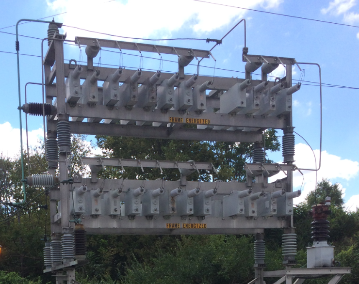
14.4Mvar, 5kV Utility Capacitor Bank
Solution: This issue of drive overvoltage fault due to utility capacitor switching can be prevented by adding a line reactor or a DC choke to the drive. Note that this will only work to prevent overvoltage fault on drives that are in operation (running condition). When the drive is in an idle ON state, adding a line reactor or DC choke may not solve the problem with capacitor switching and the drive could still fault on overvoltage.
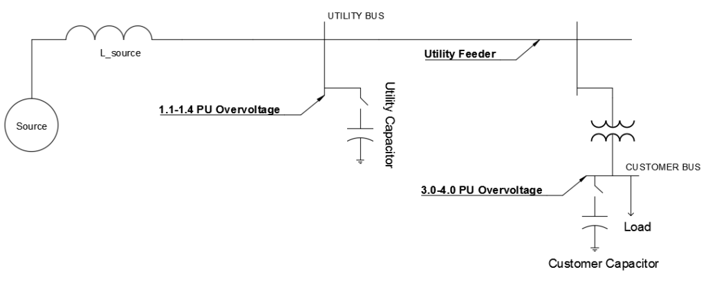
Voltage Magnification due to interaction of utility and customer capacitors
When there is customer low voltage power factor correction capacitors at customer bus in addition to utility capacitors at utility bus, high transient overvoltage condition can develop when the capacitors at utility are switched. Depending on the system resonance point and the amount of capacitance, switching a utility power factor capacitor can create overvoltage condition on the customers low voltage bus. The voltage rise will be usually larger than a pure utility power factor capacitor switching. Typically, utility capacitor switching causes 1.1-1.4 pu transient overvoltage while the same event could cause customer bus transient overvoltage up to 3.0-4.0 pu. The resulting voltage rise on the low voltage bus could trip or even damage the VFD on overvoltage.
Remember that the overvoltage protection on drives is based on the measured DC bus voltage. There is a time delay between when transient overvoltage on the AC side occurs and the time the DC bus gets boosted in voltage. Due to this time delay in protection, it is possible that the drive front end will get damaged due to these high magnitude transient overvoltage conditions.
Capacitor Switching Voltage Magnification
Solution: The solution to this problem will be to perform an analysis on the system to determine if the combination of utility capacitor and customer capacitor is creating unwanted resonance points. It may be required to change the size of capacitor bank or move it to a different location in the system-though this may not be practical to do. Other solution is to ask the utility to control the transient overvoltage at the utility bus. This can be done by using synchronous closing breakers or switches with pre-insertion resistors.
4. Input voltage with very high crest factor (Peak factor)
This is not a common occurrence and the facility voltage waveform has to be really bad for this to happen. This can be seen in really harsh operating environments like a steel plant or near any kind of arc furnace equipment etc.
Normal AC voltage waveform has a peak value of square root of 2 multiplied by the AC RMS voltage, or in other words the voltage crest factor (Peak factor) multiplied by the AC rms voltage. In an idle VFD, we can expect the DC bus capacitors to charge up to the crest (peak) of the AC voltage, which in a 480V AC system would be 1.414*480V = 678 VDC. Running VFD will have lower DC bus voltage of around 1.35*480V.
If the AC input voltage crest factor is higher than 1.414, then the DC bus capacitors will be charged to a higher voltage. Say the crest factor is 1.5 as an example. In this case, the DC bus voltage could be 1.5*480V=720V DC.
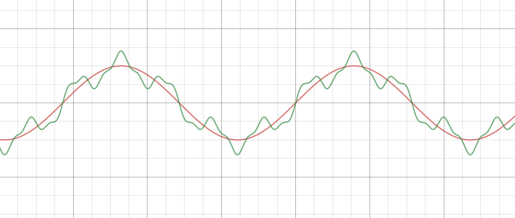
Sine wave with normal crest factor (Red) and a distorted waveform showing higher crest factor(Green)
The red graph in the figure above shows ideal ac input sine wave with ideal crest factor (Peak factor) of 1.414. The green graph shows a highly distorted waveform with significant 5th and 13th order harmonics which causes the crest factor to be 40% higher than the ideal ac input waveform. Note that the ‘peak’ of the AC voltage waveform is higher compared to the ideal case. This causes the DC bus capacitors to get charged to a higher voltage level. Under severe distorted waveform cases, this could cause the drive to trip on overvoltage fault.
Solution: The solution to this problem will be to fix the voltage harmonic issue and hence bring the voltage crest factor to a nominal value. This could involve putting additional impedance on the harmonic producing loads, harmonic filters, active harmonic filters etc.
5. Low Level System Resonance
There are two primary ways low level system resonance can happen.
Regular diode front end VFD: EMI filter circuit in the VFD can interact with system inductance to create a ‘ringing’ circuit. This ringing circuit can boost the DC bus voltage leading to overvoltage shutdown. This is a relatively rare phenomenon and does not happen frequently.
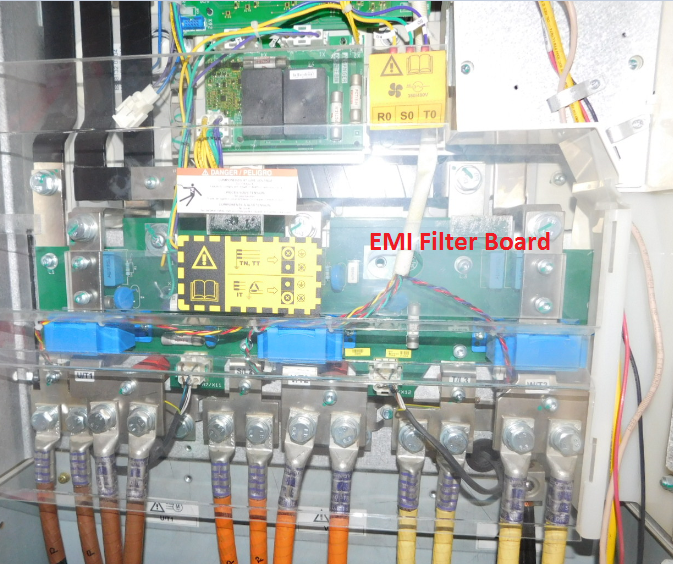
VFD With EMI Filter Board
Active front end (AFE) VFD: Remember that active front end (AFE) VFD has large L-C-L filters on the front end of the drive unlike diode front end VFD. Interaction between the front-end L-C-L filter of the AFE VFD with the power system inductance or with other AFE VFD L-C-L filter circuits can lead damaging oscillations and lead to overvoltage fault, severe damage or failure of the drive.
Active front end (AFE) VFD under idle condition create leading power factor. This is because the drive is not drawing any real watt power due to it being in idle. However, the L-C-L filter on the front end is energized. This causes each idle AFE drive to be a net exporter of capacitive reactive power in to the power network. This creates a leading power factor situation.
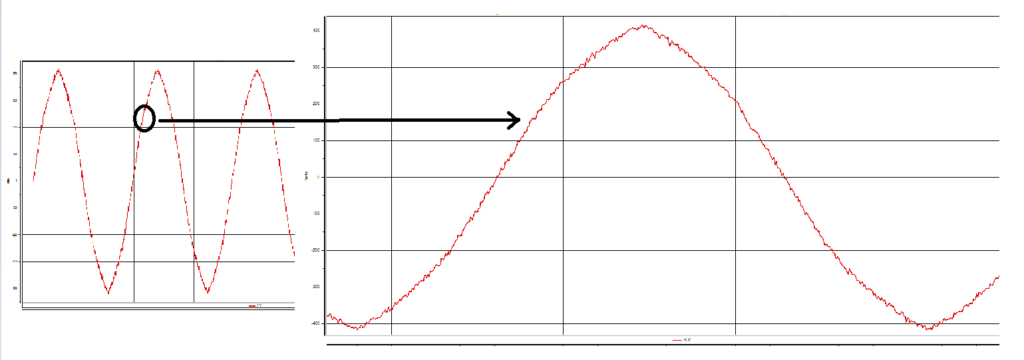
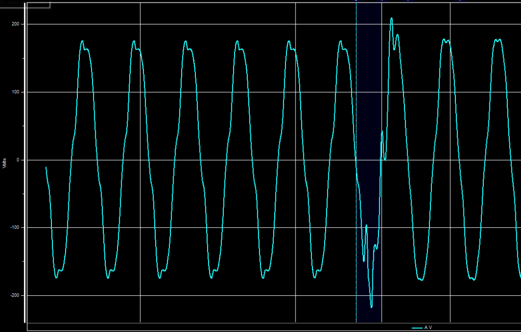
High frequency noise at 10.5kHz riding on top of 60Hz waveform- Created due to Active Front End Drives
In addition, the energized capacitors on each AFE drive can absorb noise generated by other drives which could lead to capacitor failures or fires. The ‘extra’ idle capacitance present on each idle AFE drive can amplify harmonics generated by other drives creating a low-level voltage resonance situation. If this is suspected, then this can be measured by connecting an oscilloscope to the power system. The AC voltage sine wave will show low frequency oscillations riding on the AC waveform.
The figure above shows the high frequency voltage noise created due to the operation of AFE drives. Note that the magnitude of high frequency voltage noise experienced depends on the size and number of AFE drives and the power system source impedance. Higher the source impedance (High impedance transformer, low utility short circuit capacity, generator with high reactance etc.) larger the high frequency noise voltage will be.
Solution: Low level system resonance issues are difficult to locate and troubleshoot. Troubleshooting this requires advanced power system knowledge, knowledge and qualification to use oscilloscopes etc at power system voltages. However, having knowledge that the above mentioned oscillations can occur under certain situations will aid the engineer in narrowing the possible causes.
Also read- How to measure DC bus voltage and DC bus voltage ripple