Open circuit test is performed on a transformer to measure the no-load losses and to obtain the transformer core electrical parameters namely magnetizing impedance and core loss resistance. Rated voltage is applied to the low voltage winding and high voltage winding is left open circuited. This is done for reasons of safety and convenience.
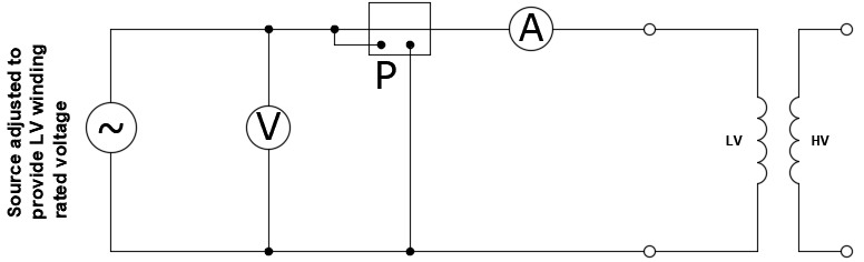
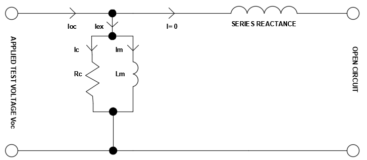
Since the second winding is open, no current flows in that winding. Hence the entire current recorded in the low voltage winding during open circuit test can be safely assumed to be going to the two branches of the core equivalent circuit, current Ic to meet the resistive no-load loss of the core and magnetization current Im to create magnetic flux in the core.
Read: Transformer Excitation Current
Resistive losses include losses such as eddy current losses, hysteresis losses. Combined total current Iex is called as transformer excitation current and flows all the time during the operation of the transformer. This current is largely independent of the secondary load.
Link to: Transformer current calculator
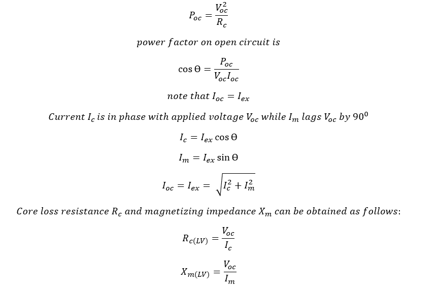
Input power Poc measured is practically equal to the core loss.
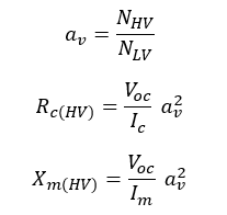
Note that the value of Rc and Xm obtained is based on transformer LV side since the measurement is done at LV. To convert the values to the HV side, it must be multiplied by the square of transformer turns ratio. Let’s define turns ratio as:
Another consideration is that if the LV side is wye connected then the test connections will be across phase-neutral and if LV side winding is in delta then phase-phase voltage is applied. This will affect the calculations of the core loss resistance and the magnetizing impedance. The transformer open circuit calculator below accounts for the wye/delta winding and uses appropriate correction factors. The calculator also provides the equivalent inductance of the core in henry (H).
A sample of transformer excitation current test results obtained by doing open circuit test at transformer factory is given below. Note that the excitation currents are in percentage of the rated full load current of the transformer and the system frequency is 60Hz.
Sample Transformer Excitation Current Test Results
| Specimen# | kVA | Primary Voltage (V) | Secondary Voltage (V) | Excitation Current (%) | No-Load Loss (Watts) |
|---|---|---|---|---|---|
| 1 | 4,000 | 13,800 | 4,160 | 0.263 | 7,790 |
| 2 | 4,000 | 13,800 | 4,160 | 0.265 | 7,743 |
| 3 | 2,000 | 13,800 | 480 | 0.258 | 3,833 |
| 4 | 2,000 | 13,800 | 480 | 0.247 | 3,797 |
| 5 | 2,000 | 13,800 | 480 | 0.254 | 3,795 |
| 6 | 2,000 | 13,800 | 480 | 0.244 | 3,712 |
Open circuit test establishes the no-load power loss of the transformer. No-load loss is an important parameter for end users as more losses mean owner of the transformer has to spend more energy to keep the transformer ON even if the load is zero. Transformers with less no-load losses are preferred for energy efficiency.
Information about the value of magnetization impedance is useful in certain transient simulation studies and to establish the reactive power requirement of power transformer.