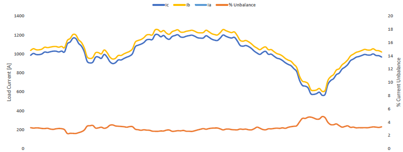
In three phase systems, current unbalance is defined as the maximum deviation of any phase current from average divided by average current. Current unbalance can occur due to reasons within the control of the end user or outside the control of end user. Some of the reasons for current unbalance (or imbalance) are:
- Source voltage from the electric utility is unbalanced
- Unequal impedance of three phase distribution system
- Unequal distribution of single-phase loads
- Unbalanced loads across each phase
- Mismatched transformer taps
- Faulty contactor, loose connection
- Single phase loss
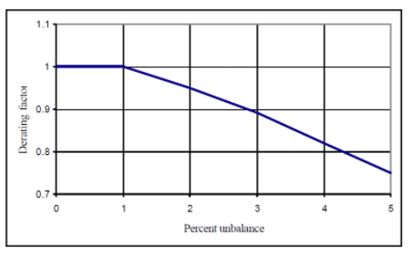
In three phase system, voltage unbalance occurs when phase or line voltage differ from nominal balanced condition. Normal balanced condition is when the three phase voltages are identical in magnitude and are displaced 120 degree vectorially. Voltage unbalance could be caused due to difference in magnitude of voltage or phase angle or both. NEMA standard for electric motor recommend maximum voltage unbalance to be 1% without any derating. Above 1% voltage unbalance, motor rated HP need to be derated (see figure 6). Voltage unbalance leads to current unbalance, overheating, damage, or reduced life in induction motors.
Link to Voltage Unbalance Calculator
Voltage unbalance can be troublesome for motor circuits especially motors that are fed across the line. Voltage unbalance in VFD fed motors also lead to current unbalance but the difference is that phase with largest voltage will carry the most current hence the VFD load has a tendency to slightly mitigate the voltage unbalance. Voltage unbalance with VFD load is discussed in the article linked below.
Link to Voltage Unbalance
From sequence components we know that unbalanced voltage will have positive and negative sequence voltage components whereas a purely balanced voltage will only have positive sequence components.
Link to Sequence Components
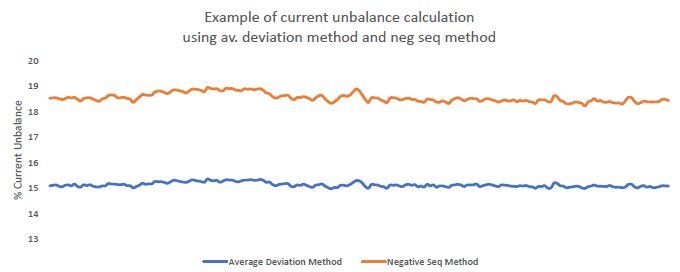
Problem with induction motor load is that negative sequence voltage will induce negative sequence current in rotor winding of motor. Induction motor has lower impedance to negative sequence current compared to positive sequence current. Typical range of ratio between positive and negative sequence impedance in induction motor is between 3 to 10.
Since negative sequence impedance of induction motor is low, a small voltage unbalance will lead to large negative sequence current in rotor windings. Negative sequence vectors rotate in opposite to positive sequence voltage vectors meaning current induced in rotor winding is twice the supply frequency (example: 120hz for 60Hz system) and will produce a torque in the opposite rotation to the desired direction of rotation. Double frequency current in rotor leads to temperature rise and can lead to winding damage. Motor temperature rise of 10o C above its rating will reduce motor expected life by 50%.
Can Time Over Current [TOC] relay protect motor from current unbalance?
Net stator RMS current increase due to voltage unbalance is not very significant and Time Over Current (TOC) element may take long time to trip. Remember it is the induced double frequency rotor current that ultimately results in motor damage. Double frequency current leads to higher eddy and core loss which TOC elements are not capable to account for. For this reason, unbalance current protection relay is recommended for induction motor.
Advanced motor protection relays have thermal models that can calculate heating effects of negative sequence currents resulting from unbalance. Thermal model calculates energy dissipated inside the motor due to locked rotor, overload, normal motor current, unbalanced current and is designated as % thermal capacity. When thermal capacity exceeds user setting, relay initiates motor trip. In applications with advanced motor protection relays with advanced thermal capacity calculation as described, current unbalance protection may be used as a backup protection.
Motor Current Unbalance Calculation
Relays calculate % unbalance by slightly different methods depending on the magnitude of average current.

Since lightly loaded motors can tolerate much higher levels of current unbalance, modern motor protective relays automatically disable unbalance protection feature when the average phase current magnitude is below 25% or 30% [manufacturer dependent].
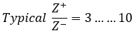
Similar to voltage unbalance calculation, current unbalance can also be calculated using two methods: Average deviation method (listed above) or as the ratio of negative sequence current to positive sequence component usually expressed as percentage [IEEE Std 1159-2009]. Some advanced power meters provide data in both formats. Calculations with both methods can yield slightly different values as sequence component method uses magnitude and phase angle whereas average deviation method only uses current magnitude. For unbalanced calculation for motor protection it is usually sufficient to use average deviation method. Figure 2 illustrates current unbalance calculation for same system using two methods.
Considerations for current unbalance trip setting
Following may be considered while arriving at current unbalance trip setting for motor relays.
- Single Phasing
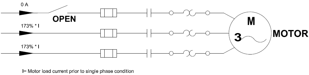
Single phase condition produces the worst current unbalance condition in induction motors. If not protected adequately against this possibility, motors can get damaged in a matter of few minutes. When a motor that is loaded to its capacity experiences single phase condition (loss of one of three voltage connection), motor will try and continue to produce rated power output. By doing so the phases that are healthy will carry 173% of the pre-fault load current.
If motor is adequately protected per its rated FLA and pre-fault load is close to FLA, then protective device (circuit breakers or fuses) will trip on this 173% over current condition quickly.
A possible scenario where normal motor overload protection could fail detecting single phase condition is when motor is lightly loaded. Say for example motor is only loaded to 50%. Then motor current in per unit will be 1*0.5= 0.5pu. Healthy phases will see 0.5*1.73= 0.865 pu of current only. An overcurrent circuit breaker or fuse rated for rated 1pu FLA will not trip. However, a properly set motor unbalanced current relay can easily detect and clear this condition. For this example, motor loaded to 50% with one phase lost will result in 58% current unbalance. Typical motors relays are set to trip in the range of 15-20% and will easily detect this condition.
Graph below shows percentage current unbalance for various single-phase conditions.
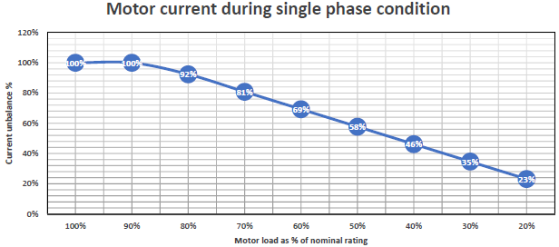
Referring to figure 4, when a motor loaded to 60% experiences single phase condition, current unbalance will theoretically be 69%. If motor is capable of running at low loads, then it is important to NOT set unbalance current pickup too high.
- Utility voltage unbalance
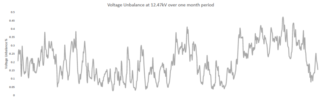
While programming current unbalance settings on protection relays it has to be kept in mind that 1% voltage unbalance causes approximately 6% current unbalance in induction motors. Unbalanced voltage of up to 0.2-0.5% are common for utility supply. They could be higher at 1-2% in some rare cases.
If 2% voltage unbalance exists at a location, then set unbalanced current protection atleast above 12% in addition to derating the motor in accordance with NEMA derating factor (see figure 6).
- Utility faults
Utility faults, lightning strikes, reclosing etc result in short term voltage unbalance that could lead to short term motor current unbalance. Utility faults and reclosing usually last anywhere from 50ms to 5s. Programming suitable time delay in unbalance current relay is important to avoid nuisance trips for such situations.
Considering the scenarios mentioned in case ‘1’, ‘2’, ‘3’, current unbalance trip is typically chosen between 15-25% with a delay of 10-20s. An alarm setting of 10% with a delay of 10s may also be considered. These are typical values and users are encouraged to review each application on a case by case basis.
Link to Motor Current Calculator