In three phase systems, voltage unbalance or voltage imbalance occurs when the phase or line voltages differ from the nominal balanced condition. Normal balanced condition is when the three phase voltages are identical in magnitude and phase angles are displaced 120 degree vectorially. The unbalance could be caused due to the difference in magnitude of the voltage or the phase angle or both. From a reliability and power quality aspect having a good voltage balance in the system is paramount.
Link to Current Unbalance
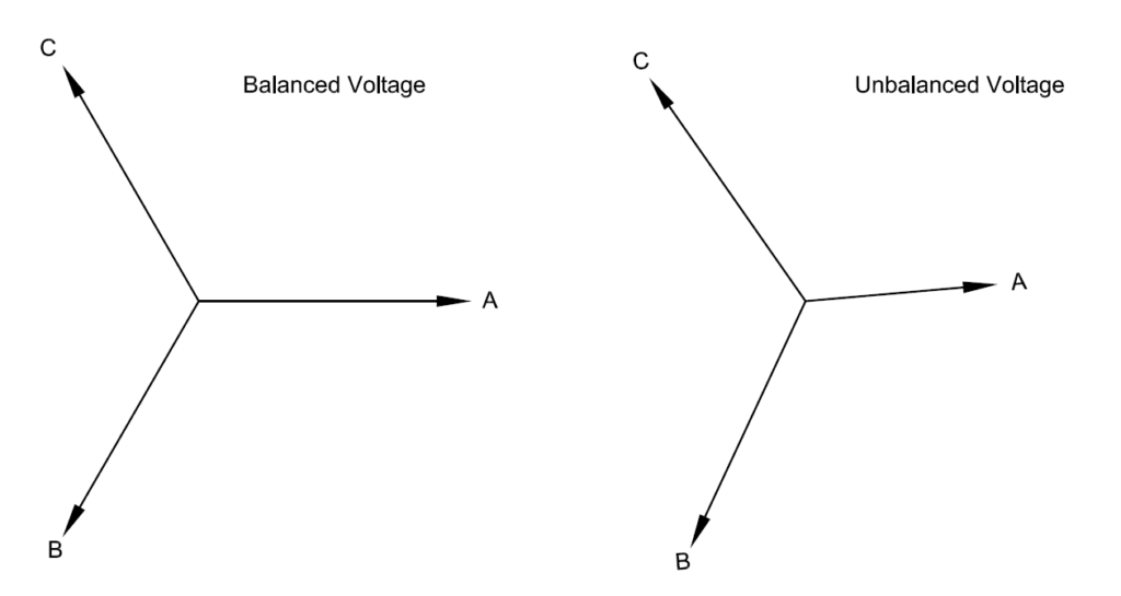
Balanced and Unbalanced Voltage vectors
Following are some of the factors that could contribute to voltage unbalance:
- Source voltage from the electric utility is unbalanced
- Unequal impedance of three phase distribution system
- Unbalanced loading on power factor correction capacitors [Like blown fuse on one phase]
- Unequal distribution of single phase loads
- Unbalanced loads even if connected in three phase
- Mismatched transformer taps
Following are some of the effects of having voltage unbalance.
- Increased heating and reduced life of induction motors
- Reduced life of VFD front end diodes and or bus capacitors.
- Depending on the type of load, reduced voltage could lead to increased current in one or more phases and hence increases losses.
The above points will be discussed in detail after the definition of voltage unbalance is introduced.
Definition of Voltage Unbalance or Voltage Imbalance:
There are two commonly used definitions of Voltage Unbalance in the industry. These are:
NEMA Definition: NEMA stands for National Equipment Manufacturers Association in USA. NEMA definition of voltage unbalance is given by:
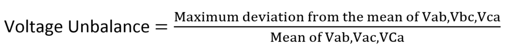
NEMA definition is also called Line Voltage unbalance rate (LVUR) since Line voltages (i.e. Phase-Phase voltages) are only used for calculation. Line to neutral voltage should not be used as zero sequence components can give incorrect results. Additionally, phase angles are not included in the equation. As can be observed, calculating the NEMA voltage unbalance is relatively straightforward.
The following calculator can be used for calculation voltage unbalance based on NEMA method.
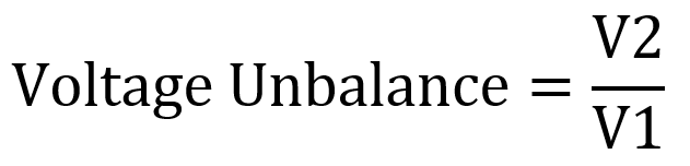
True Definition: This definition of voltage unbalance is also known as ‘True definition’ , ‘IEC Definition’ or ‘Voltage Unbalance factor’. Based on this, the percent voltage unbalance is defined as the ratio of negative sequence voltage (V2) to the positive sequence voltage (V1).
If you are wondering what negative and positive sequence voltages are, here is a simple explanation. Three phase voltages (or currents), balanced or unbalanced can be mathematically expressed as a sum of positive, negative and zero sequence components. It is a mathematical technique that is used extensively in power system engineering and its details can be found in many power engineering text books. For example, if we have an unbalanced voltage that is vectorially represented as shown below it can be separated in to its constituent positive, negative and zero sequence components as shown. Out of these we will use the negative and positive sequence voltage magnitudes to calculated the unbalance. Note that positive sequence voltage creates flux in the direction that the motor is intended to rotate. Negative sequence voltage rotates in the opposite direction (vectorially) from positive sequence and hence creates flux in the opposite direction. The positive sequence voltage will be much larger than the negative sequence and hence the direction of rotation of motor is not affected. However, the counter rotating negative sequence flux will create additional heating in the motor.
Why zero sequence voltage unbalance is not used? This is because, zero sequence currents cannot flow in induction motor loads that are most affected by voltage unbalance. Induction motor windings are almost always connected in delta or ungrounded wye. Hence calculating the zero-sequence voltage unbalance is not very useful practically.
Below is a calculator that can be used to calculate the voltage unbalance using the true definition or the IEC definition. The calculator calculates the positive, negative components of the system voltage and uses that to estimate the ‘true’ voltage unbalance.
There could be difference in the %unbalance calculated by both the methods which is perfectly normal. NEMA definition does not account for phase angles and hence this can be expected. Induction motor will always respond to the ‘true’ value of the voltage unbalance as this is the only equation that uses both positive and negative sequence voltages. Negative sequence is at the core of producing counter rotating magnetic flux inside the motor and the resulting heating.
Effects of voltage unbalance
Induction Motors: Perhaps the one device that is most affected by voltage unbalance is the old and trust worthy induction motor. When a three motor is fed with an unbalanced voltage, the line currents are usually several times the voltage unbalance percentage wise. That means a motor fed with say 5% voltage unbalance could have 20-30% current unbalance. The additional current will cause resistive (I2R) losses in the motor which results in temperature rise. Temperature is the number one killer of motor insulation. It is estimated that the insulation life of motor is cut in half for every 10 degree Celsius increase in winding temperature.
NEMA has developed derating curves for motor operating under unbalanced voltage conditions. Curve assumes the motor is delivering the name plate rated load.
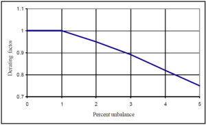
From the curve it can be seen that any motor should be able to tolerate up to 1% voltage unbalance without derating. For a 3% unbalance the motor should be derated to 0.9. Operation of motor above 5% voltage unbalance is not recommended.
Variable Frequency Drives:
Variable Frequency Drives are becoming more and more common in industrial and commercial establishments as a means of controlling the motor speed in an efficient manner. It is rather not a well known or understood that voltage unbalance can be bad for the variable frequency drives as well. As a matter of fact, other devices that uses similar front end circuit with diode rectification also tend to have similar issues with unbalanced voltage. These could be three phase UPS, large DC power supplies with three phase input etc.
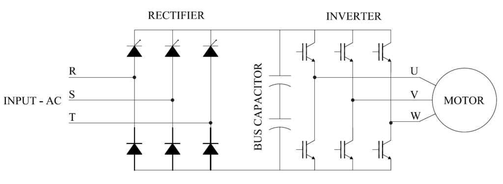
Three phase diode front end circuits like the one shown above draw current in pulses. For a 6 pulse drive which is the most common drive in use, we can see 6 pulses of current in one AC cycle. Each pulse of current occurs when the AC supply voltage is greater than the DC bus capacitor voltage.
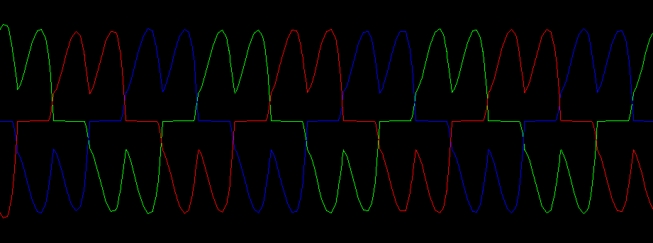
6 pulse waveform- Balanced Voltage
When the supply voltage is balanced, each diode conducts the same amount of current for the same duration. The area under the current waveform essentially represents the power required to operate the load connected to the VFD.
As the voltage unbalance increases, one or more diode will stop conducting and the current drawn will look like a single large pulse similar to what is seen in single phase power rectifier. The large pulse of current will now be only shared with fewer diodes thereby over stressing the diodes. Since the power delivered to the load is a constant value, the area under the current waveform has to remain the same. Additionally, supply voltage unbalance will also cause the DC ripple in the DC bus capacitor to increase thereby creating additional heat loss and decreased service life for the bus capacitor. Depending on the settings the drive may trip on overcurrent or DC bus undervoltage.
Each time a pair of diode conducts, it will draw a large pulse of current as discussed above. This is essentially connecting a capacitor to supply, wherein a large pulse of current, the magnitude of which will depend on the existing charge on the capacitor as well as the source impedance. If one phase has a slightly higher impedance compared to the other phase, then that is usually reflected in the current pulse. Note that in the figure below, C phase has 1ohm resistance while the other two phase have 0.1ohm. Note the difference in the magnitude of current draw for each pulse.
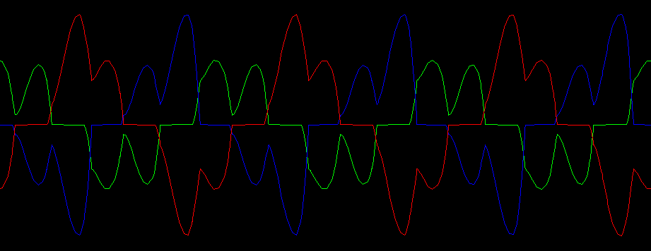
6 pulse waveform with unbalanced voltage
The difference in the current pulse height of AC variable frequency drives is usually a sign of :
- Supply voltage unbalance
- Supply impedance of one or more phase being different compared to the healthy phase.
Supply impedance could be different between one or more phases due to:
- Loose connection anywhere on the source supply.
- Upstream transformer impedance mismatch between different phases. This is usually rare for three phase transformers. However, for three phase transformers assembled using three single phase transformers this is a possibility unless the impedance are closely matched.
Methods to reduce three phase voltage unbalance at a plant level:
- Distribute single phase loads evenly.
- Use three phase voltage regulator. Look for devices that has independent phase regulation. At low voltage these are available between 5kva to over 2,500kva.
Solutions to consider to mitigate effects of three phase voltage unbalance at an equipment level:
- Three phase voltage regulator. Look for devices that has independent phase voltage regulation.
- Three phase double conversion UPS: A double conversion UPS always powers the load from the battery. That means battery is the primary source of output power and the AC input is used to charge the battery. Line voltage disturbance or unbalance will not affect the load. However, each UPS manufacturer will a level of input voltage unbalance that the front end rectifier section can tolerate. This parameter needs to be compared with the facilities existing voltage unbalance to make sure UPS will operate as intended.
- Three phase delta conversion UPS: These exhibit similar advantages as the double conversion UPS but offers improved efficiency of operation. Delta conversion also has advantages with reduced harmonic current on the supply side.
- If the voltage unbalance is created due to large single-phase motors, considering adding passive or active var compensation (Power Factor Correction). This will only work if the reactive power draw of the single phase motor is causing the voltage unbalance. Passive compensation will be to add power factor correction capacitors at the motor. Single phase motor power factor capacitors are available and these are typically connected to the load side of the motor disconnect.
Methods to protect motor or equipment from damaging effects of voltage unbalance:
- Phase balance relay: Use phase voltage balance relay to trip the motor/load in case of excessive voltage unbalance. Both single phase and three phase phase balance relays are commercially available. Typically these relays offer additional protection such as phase voltage loss, phase sequence protection etc.