Drive (VFD) undervoltage protection for common low HP drives is based on the measured voltage on the DC bus of the drive unit and not the input AC voltage. It is important to realize this fact to aid in troubleshooting. Any and all events that could cause a dip in DC bus voltage could lead to a dc link undervoltage fault event. This guide will help you in troubleshooting VFD problems with undervoltage fault code.
The ideal DC bus voltage for a 3 phase VFD under idle (not running) condition should be approximately square root of 2 multiplied by the AC RMS voltage. Hence for a 480V, 3 phase system the expected idle DC bus voltage should be around 678V. For a 415V 3 phase system drive the idle DC bus voltage should be around 586V. The actual value of DC bus voltage is dependent on many parameters including:
- AC input peak voltage
- Load on the drive
- Presence of AC Line Reactors
- Presence of DC Choke
- Presence of Isolation Transformers
Due to the above factors, DC bus voltage under normal condition could vary a lot. Typical nominal values are:
- 230V System: 310 VDC
- 415V System: 560 VDC
- 480V System: 648 VDC
- 600V System: 810 VDC
Measuring DC bus voltage require knowledge of the expected DC voltage magnitude and availability of equipment rated to withstand that voltage. Most drives will provide magnitude of the DC bus voltage on the drive display screen or this can be measured at designated terminals on the drive.
The undervoltage threshold at which fault is triggered will vary between manufacturers. Here are few manufactures undervoltage fault thresholds:
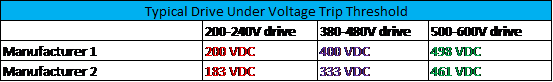
VFD undervoltage trip thresholds
Comparing undervoltage trip thresholds with the nominal DC bus voltage we can see that the undervoltage trip settings for most drives is around 60% of nominal DC bus voltage. Corresponding approximate AC voltage at which undervoltage fault occurs can be calculated by dividing the above values by 1.35.
Typical Reasons for having DC Bus Undervoltage Fault on VFD
- Steady state undervoltage
- Momentary voltage sag (dip)
- Loss of one phase
- Problems with precharge circuit
- VFD DC voltage sensing circuit malfunction
Each of these are discussed below.
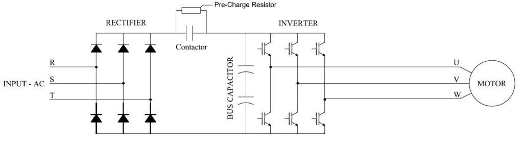
VFD Schematic with Precharge circuit
1. Steady state undervoltage: In this scenario, the voltage at the facility bus is less than the nominal value. When the VFD input voltage is low, DC bus voltage would correspondingly go down. The ripple on the DC bus would increase as well. If the DC voltage goes below the threshold then drive would fault on undervoltage.
Solution: The solution for steady state undervoltage would be to contact the electric supply company to check if changing the supply transformer tap position or adjusting voltage regulator is a possibility. If the facility owns the step-down transformer then investigate possibility of changing the transformer tap to increase the voltage. Additional review is recommended before adding any power factor correction capacitors for boosting the system voltage. When the system has large non-liner loads (VFD etc) the capacitors can interact with the harmonics produced by the drive to create harmonic resonance issues. Resonance could lead to capacitor and/ or VFD failure. In these situations, detuned capacitors are recommended.
If the steady state voltage at the drive is slightly lower than nominal then the drive voltage setting parameter can be changed to that value. As an example, if the input voltage is 460V instead of 480V, then having the drive voltage parameter programmed as 480V will cause the undervoltage trip threshold to the higher than if it was programmed for 460V. This is because the undervoltage trip setting is based on programmed input voltage.
2. Momentary voltage sag (dip): Voltage sag or voltage dip is a variation in the rms voltage of duration greater than ½ cycle and less than 1 minute with a retained voltage between 10% and 90% of nominal according to IEEE Std 1159 definition. Momentary voltage sags can be detrimental to the operation of the drives. There are couple of problems created by voltage sags. These can be classified in to two:
Primary effect
- Undervoltage fault
Secondary effects
- Fuse /circuit breaker tripping
- VFD rectifier diode/capacitor failure
Primary effect: A momentary voltage sag can cause DC bus voltage to go low and reach the fault threshold and trigger shutdown of drive.
Secondary effect: Depending on the load on the VFD, a momentary voltage sag could cause the DC bus voltage to fall below the fault threshold. During the voltage sag (dip), the energy for the motor is derived from DC bus capacitor causing it to be depleted faster than normal. Upon restoration of voltage (when voltage sag is over), a large inrush of current occurs from the AC input side to charge the drive bus capacitors. Depending on the size of the drive this current peak could be 5-20 times the normal peak current of the drive. This large inrush of current can cause the fuse or circuit breaker feeding the drive to trip out. In addition, the surge current could also damage the diode rectifier circuit and capacitor especially if drive is applied close to a large kVA source transformer.
Solutions to mitigate voltage sag:
Voltage sag mitigation at a system level: Mitigating voltage sag at a facility level is accomplished using sag mitigation techniques. Some of these are:
- Dynamic Voltage Restorer [DVR]
- Static Var Compensator [SVC]
- Sag Proof Transformer
Voltage sag work-around at VFD: Many modern VFDs have the capability to perform some sort of sag ride through feature. This means the drive will be able to ride through the voltage sag with some loss of performance for a brief duration. These are manufacturer specific and it is recommended to consult the corresponding drive data sheet for more information. Some of the common options on modern drives include:
- Upon initiation of voltage sag the drive will continue to operate from the stored energy in the DC bus until the DC voltage drops to a preset value. This allows the drive to provide power to the motor during brief voltage sag events. If the sag persists and the DC bus voltage falls to a predetermined threshold then the drive will trip off on undervoltage.
- Upon initiation of voltage sag the drive will stop powering the motor and will try to maintain DC bus voltage as long as it can using the motor inertia. By doing so the VFD can be kept online without tripping though the motor will start slowing down.
- If the drive has a undervoltage fault delay setting then it can be used to delay the fault occurrence.
Solution to mitigate secondary effects of voltage sag on VFD:
Preventing fuse operation, diode failure: The input fuse or circuit breaker operation after a voltage sag (dip) is due to the surge of current drawn by the discharged DC capacitors. The surge current magnitude can be reduced and hence the chance of fuse operation and diode failure reduced by applying the following:
All the components listed above adds additional impedance on the supply side of drive and hence reduce the peak charging current magnitude. Reducing the peak charging current after a voltage sag will help prevent fuse operation as well as diode failures and even premature capacitor damage.
3. Loss of one phase: This situation could arise if after a storm one phase of the electric utility has opened or the facility has been single phased due to either fuse operation or some other causes. When a drive loses input voltage, it will either detect as input phase loss fault or undervoltage fault depending on the design.
If the drive that has lost one phase is continued to operate (either by defeating the phase loss parameters settings or other means), then the drive will draw larger peak currents in the other two healthy phases. This will also increase the ripple voltage on the DC bus and may lead to failure of rectifier diodes or capacitors on the drive. It is not recommended to turn off the phase loss parameter.
Solution: There is nothing much that can be done to prevent single phasing on the electric utility lines. However, the facility can install phase loss relays at the incoming service switchgear and shunt trip the main breaker. The drive phase loss parameter needs to be turned ON to protect the drive from damage due to single phase condition.
4. Problems with pre-charge circuit:
On many modern drives (not all drives have this feature), there is a pre-charge relay that charges the DC bus capacitor through a series resistance. See the figure at the beginning of this article. This circuit is to prevent large inrush of current in to the discharged DC bus when the drive is initially switched ON. After a preset time delay at which time the DC bus would have charged to the required voltage, the resistor is bypassed using a contactor and is no longer part of the circuit.
If there is any problem with the contactor switching back from resistor then the full current draw will be through the resistor and the DC bus voltage will be low to support the load and may trip on undervoltage. This usually occurs during the starting stage of the VFD. This problem usually will lead to the pre-charge resistor failing quickly if the drive is restarted couple of times.
5. Problems with VFD DC voltage sensing circuit
The undervoltage and overvoltage fault settings of the drive are based on measured voltage from the DC bus by the drive control circuitry. If there is any malfunction in this circuit it could lead to nuisance under or overvoltage trip.
If this is suspected then the DC bus voltage needs to be measured and compared against the value on the drive display screen. Read ‘How to measure DC bus voltage and DC ripple’ for more information on DC bus voltage measurement.
Also Read: VFD Input Current Vs Output Current