Potential Transformer Definition: Potential transformers (PT) or Voltage Transformers (VT) can be defined as devices used to step down voltage from high voltage typically used in transmission and distribution to a low voltage (typically between 50-150V). By using a PT, voltage is reduced that can be safely handled by meter or relay circuits. Potential transformers are connected ‘parallel’ to the system that we intent to perform the measurement and should offer negligible loading to the high voltage power system that it is connected to. Terms PT and VT appears to be used interchangeably though VT is the new terminology.
Potential Transformer Accuracy Class
Typical ANSI Potential Transformer accuracy classes are 0.3, 0.6 and 1.2. Standard IEC accuracy classes are 0.1, 0.2, 0.5, 1. PT mainly introduce two types of errors that affect the accuracy of the measurements:
Ratio Error
Phase Angle Error
In a given PT, the metering error is a combination of two separate errors listed above. This combination is called Transformer Correction Factor (TCF). IEEE C57.13 has established accuracy classes for PT and require that limits of permissible error remain constant over a range of voltages from 90% to 110% rated voltage from zero to the specified standard burden at the specified burden power factor. In practice, performance at voltages down to 5% are not significantly different with the same burden connected at the PT secondary. Error limits required by IEEE C57.13 apply not only at a given burden, but also at zero burden. Errors on the PT circuit and CT circuit both contribute to a net error in the energy measurement, power factor measurement etc. Let’s discuss in detail what these errors are and how to calculate them.
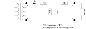
Ratio Error: A PT with 4,160V/120V ratio has a PT ratio of 34.66. So, when 4,160V is applied on primary we should see 120V at the secondary- ideally. When a PT is loaded with a burden (load) current flows in the circuit. This current flowing through the series impedance of the PT lead to a small voltage drop which subtract from the ideal voltage output. Series impedance of the potential transformers are normally quite small. At standard burden, the manufacture would have adjusted the transformer winding to deliver standard nameplate output voltage for that accuracy class and should not be a concern. At any other burden the voltage ratio would be off slightly.
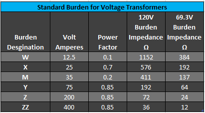
The maximum ratio deviation over a specified range of burden defines the accuracy class of the transformer. If the maximum ratio error is +/-0.3 % over the standard burden range, the PT or VT is said to be 0.3 accuracy class. Standard burdens are listed below.
PTs are designed so that the impedance ZH is as low as possible since they are responsible for the ratio error in a PT. PTs are designed to operate at a high voltage on the saturation curve unlike current transformers. A compromise in design is required in the design as higher the voltage, higher the exciting current (through Rm and Xm) which lead to larger voltage drop in the primary impedance causing ratio and phase angle errors. For limiting the current through the exciting impedance (Rm, Xm), PTs are designed to work without excessive exciting current up to 110% of rated voltage.
Ratio Correctio Factor (RCF): Potential Transformers may have a marked ratio of some number (say 4 for 480/120V PT). The actual voltage at the secondary could be slightly higher or lower than the marked value. This ratio is defined in IEEE C57.13 as Ratio Correction Factor (RCF). For example, if the marked PT ratio of a PT is 20 but the actual ratio is 20.2, then the RCF is [1+ (20.2-20)/20] = 1.01 or in other words the ratio error is 1%.
Phase Angle Error: Phase angle error is a problem when watts, Var (PF) and impedance are to be measured. For PT, phase angle error is expressed in minutes rather than degrees. For very light burdens, the secondary voltage may lead the voltage being measured, but in most practical applications, phase error will be lagging (-ve). Voltage transformers (VT or PT) are usually supplied with charts or circle diagram that show the ratio and phase errors as function of burden magnitude and power factor.
Potential Transformer Circle Diagram
PT or VT circle diagram are an easy method of determining accuracy at any burden and power factor. Radial lines represent different power factors for the PT burden. The concentric circles are the burden in VA (volt-amperes).
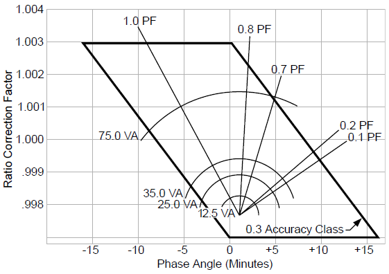
PT accuracy can be determined from the circle diagram using the following steps:
Find the power factor of the burden used in the PT secondary circuit.
Determine the VA rating of the load burden.This is provided by the relay/meter manufacturer as to how much burden VA their equipment adds to the metering circuit. If multiple meters/relays are connected then individual VA may be added in series to determine the total VA loading.
Move vertically on the identified power factor line up to where it hits the VA rating. Ratio Correction Factor and Phase Angle error can be determined from the x and y intercept of the circle diagram.
As an example, a PT rated for 0.3 WXMYZ will maintain a 0.3 accuracy class from 0 VA to 200 VA (Z burden). PT accuracy changes linearly with burden. At factory accuracy is recorded at zero and full burden and this data can be requested from the manufacturer. Between these two points a ‘load line’ can be drawn. By scaling the length, accuracy at any intermediate value of burden can be obtained.
For example, if a PT rated with ‘Z’ burden or 200VA was loaded only at 100VA, the accuracy point would be in the center of the load line drawn between maximum and zero burden points. From the load line, the Ratio Correction Factor (RCF) and phase angle error can be obtained.
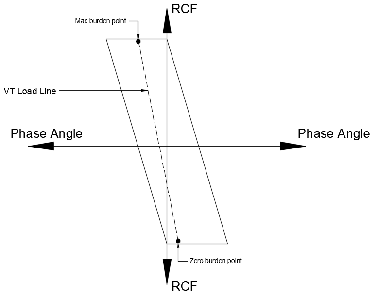
Since modern digital meters and power meters burden is very low, the accuracy of the VT/PT can be improved using a VT with lower full load burden. Referring to the figure above loading a 0.3WXMYZ (200VA) VT with only 15VA of actual burden puts it at the bottom portion of the accuracy graph. Instead, if 0.3WXM (35VA) was chosen, then the 15VA actual burden would be in the middle of the graph with near unity RCF and near zero phase angle error, a smaller and cheaper solution.
The upper and lower limits of RCF and Phase Angle per IEEE C57.13 is given in the table below.
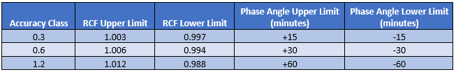
For a given accuracy class, the PT characteristics need to lie within the bounds shown on the table above from all voltages between 90% to 110%.
Other Considerations:
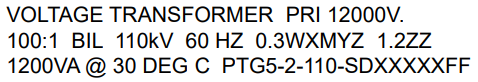
Potential Transformer nameplate details and other details are discussed here.
Ratio: PT ratio is the ratio of primary voltage to the secondary voltage. If a PT is marked 14,400:120V, then applying 14,400V at the primary will result in 120V across secondary winding. At lower primary voltage, secondary voltage will be reduced proportionally. PT can be connected at a lower voltage and also in a three phase configuration, Delta-Delta, Delta-Wye etc.
Additional information on PT ratio calculation and three phase PT connection is provided here. PT polarity testing is discussed here.
PT thermal Rating: Thermal rating is the maximum burden in VA that the transformer can carry at rated secondary voltage without exceeding the temperature rise. If no thermal burden in VA is given, the thermal burden rating in VA shall be the same as the maximum standard burden for which an accuracy rating is given.
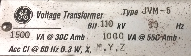
Referring to the name plate above, the thermal rating is 1,500VA at 30 deg C ambient or 1,000VA at 55 deg C ambient.
PT Overvoltage Rating: IEEE standard allows for two levels of operation. One for continuous and other for emergency conditions. A PT must be capable of operating at 110% above rating voltage continuously provided secondary burden at this voltage do not exceed the thermal rating. Emergency rating of PT is defined at one minute of operation, thereby giving enough time for protective equipment to operate. Refer to IEEE c57.13-2008 for details on the various overvoltage classifications.
Insulation Class: Industry recommendations are that the insulation class of an instrument transformer should be atleast equal to the maximum line-line voltage existing at the point of connection.
Polarity: Voltage Transformer (or PT) polarity is covered in this article.
Potential Transformer Connections
Below are some of the common types of potential transformer (PT) or voltage transformer (VT) connections:
Delta-Wye
Delta-Delta
Wye-Wye
Open Delta
Broken Delta
Delta secondary or open delta connection may be used for measuring line-line (phase-phase) voltage. Line-neutral voltage cannot be obtained using this connection. If line to neutral voltage is desired to be measured then one of the wye connections may be used with the neutral grounded. Additional attraction for wye-wye connection is that individual PT need to be rated only for line-ground and thereby less expensive compared to line-line rated PT if the connection was done in delta fashion. For this reason, it is common to see wye-wye connections in medium voltage (>1000V) applications.
A calculator for obtaining secondary PT voltages for various winding configurations can be found here.
Per IEEE C57.13, PT connected line-ground on an ungrounded system cannot be considered a grounding transformer and shall not be operated with the secondary windings in closed delta because excessive currents may flow in delta secondary. This is because by having the PT primary connected line-ground in an otherwise ungrounded power system, a ground path for harmonics and other zero sequence current is provided. If the secondary of such a PT is connected in closed delta then the zero sequence currents (that enters the primary) will have a closed circulating path within the delta secondary. This current is confined to the delta windings and will not show up on the line currents. Overtime this circulating current if excessive can overheat and damage the PT.
Connecting line to ground PT on an ungrounded system may also tend to drift in to damaging ferroresonance depending on the amount of cable capacitance and damping. A related but different phenomenon can also occur when line-ground PT / VT is applied on an ungrounded system. This is called neutral inversion and is discussed in this article.
Broken delta is used for special zero sequence relaying applications and not in metering.
Voltage Transformer Burden Calculation
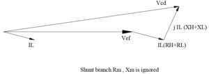
If the PT is loaded below the standard burden, then accuracy of selected PT is guaranteed for that application. If however the secondary leads are very long or burden is very large then the cable will introduce additional voltage drop and error. If the resistance and inductance of the lead wires are RL and XL respectively and the power factor angle is Ɵ, the % accuracy will go (become worse) up by:
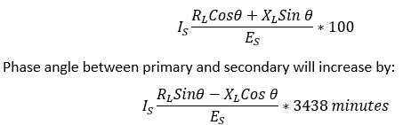
This phase angle needs to be added algebraically to the phase angle of transformer to get actual phase angle difference.
Terminology Roundup:
Transformer Correction Factor (TCF): Correction for the overall error due to both ratio and phase angle error for a specified load power factor. For voltage transformers (PT) TCF at 0.6 power factor is defined as:

Ratio Correction factor (RCF): The ratio of true ratio to the marked ratio. If a PT has a marked ratio of 480V/120V (ratio of 4), but the actual ratio is 480V/122V(ratio of 3.934), then RCF can be computed as 3.934/4 = 0.9836. Multiplying the actual secondary voltage (122V in this case) by the RCF (0.9836) yields the corrected output (122*0.9836=120V).
Potential Transformer Standard Burden: The maximum load in volt amperes (VA) at a certain power factor that may be placed on the potential transformer or voltage transformer secondary without causing an error greater than allowed by the standard. For example, a 0.3WX PT can have a burden of 25VA at a power factor of 0.7 and still have 0.3% accuracy. Refer to the standard burden for voltage transformers given in this article.
Accuracy Rating: A PT will have accuracy rating stamped on the unit. For example, an accuracy rating of 0.3 WXMYZ 1.2ZZ implies the PT has an accuracy rating of 0.3% over any of the burdens listed (12.5, 25, 35, 75 VA respectively) and accuracy of 1.2 over ZZ burden (400VA). Another example is 0.3WX 0.6Y 1.2Z which means the PT has accuracy of 0.3 over W and X burdens, 0.6 accuracy at Y burden and 1.2 accuracy at Z burden.
Other Articles: Broken Delta, Transformer Connections:Phase Shift and Polarity, Open Delta, Neutral Inversion, PT Ratio Calculation