Transformer Differential Protection Basics: Differential protection of transformers provide complete protection of transformer. Differential protection is possible due to the high efficiency of transformer operation and the close equivalence of ampere turns developed on the primary and secondary windings. Current Transformers (CT) are connected to the primary and secondary windings of the transformer to form a closed circulating path.
Differential protection works on the principle of Kirchhoff’s Current Law (KCL). This law states that the total sum of current flowing in to a node is zero. If the per unit primary side current is equal to per unit secondary side current, then KCL is verified and no fault is present in the transformer. This is the basic working principle of a transformer differential protection relay.
Differential protection offers fast and reliable protection of critical asset such as a transformer. Differential protection is also used in protecting other high value assets such as medium voltage motors, reactors, switchgear etc. Differential protection in a transformer provides superior protection against:

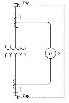
Protective relay coils are connected as shown in the figure below. The coils identified as ‘R’ is known as restraint coil and coil identified as ‘O’ is known as operate coil. When there is a fault in the zone of protection, the restraint current and operate current increases. When the operate current is above the transformer percentage differential characteristic trip curve, a trip command from the relay is issued. Note the polarity face of the CT. It is common to have CT polarity as shown though other combinations are also possible. In the shown configuration, ratio current from the primary and secondary CT are 180 degrees out of phase during normal loading. Two cases can be considered:
Case 1: Normal loading of transformer or external fault: In this case both primary and secondary CT produces current in the direction shown. In the common branch the current sum to zero and hence the protective relay does not see any error current. This is error current is known as Operate current. The current that flows through restraint coil is known as restraint current.
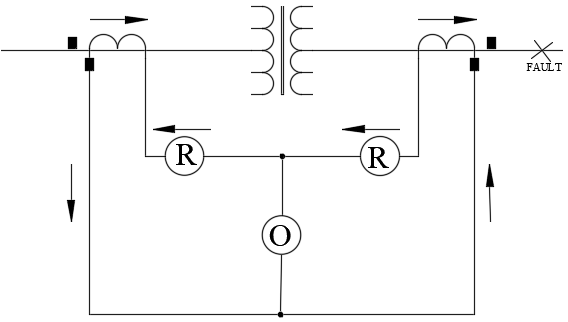
In other words, during normal loading or external faults, all CT ratio current flows through restraint coil and none flows through operate coil.
Case 2: When there is internal fault: In this case the currents produced by the primary and secondary CT do not sum to zero and hence there will be a net error current or operate current. The protective relay will detect this current and trip the appropriate transformer primary or secondary breakers.
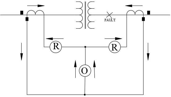
In other words, during internal faults, CT ratio current flows through restraint coil and through operate coil. If the operate current is above the percentage differential setting threshold, the relay will issue a trip command.
Transformer Differential Protection Setting Calculation
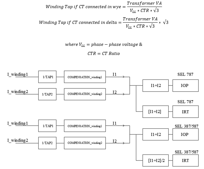
Transformer Differential Protection Scheme works by using two separate quantities calculated from the primary current (IW1C) and secondary current (IW2C). SEL787 and SEL 387/587 Transformer differential relay is used for this discussion. Other similar relays use similar concepts through the actual terminology could be different. Some of the parameters relevant to this discussion are:
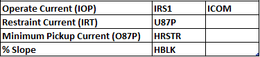
These quantities are calculated as follows.

IOP is calculated as the vector addition of primary and secondary currents whereas IRT uses just the magnitude of the currents to calculate the restraint quantity.
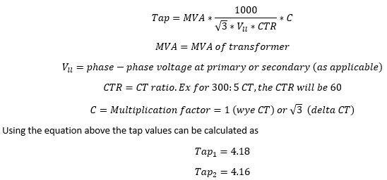
Internal to the relay the primary and secondary CT secondary currents are converted to per unit ‘winding tap’ value. The equations for per unit conversions are:
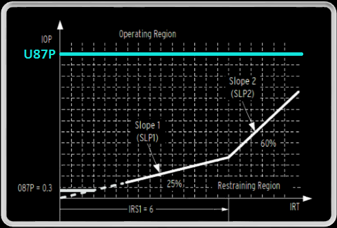
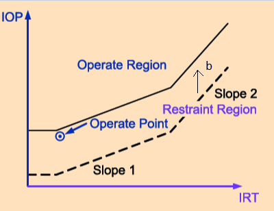
As discussed, the relay calculates the operate current (IOP) and the restraint current (IRT). Operate region is the area above the curve where the relay will trip and restraint region is the region below the curve where the relay will restrain itself from tripping. Increased loading of the transformer will move the restraint (IRT) horizontally to the right on the ‘x’ axis with no change in operate quantity (IOP) whereas a short circuit fault will move the IRT to the left and the IOP up on the ‘y’ axis. If the resulting coordinate of (IRT, IOP) on the x-y plane falls above the percentage differential characteristic, tripping will occur. If the (IRT, IOP) coordinate falls below the curve then no tripping occurs. Tripping behavior of the relay is based on the relay percentage restraint differential characteristics. The purpose of percentage restraint is to allow the relay to differentiate between differential current resulting from an internal fault versus differential current resulting from normal current or from external fault. The key points in the graph above are:
Minimum pickup current (087P): This value is usually set between 0.3 and 0.5 per unit. This value provides security against CT remanence and accuracy errors. The setting must be at a minimum for increased sensitivity but high enough to avoid operation because of steady state errors such as unmonitored station service loads, transformer excitation current and relay measuring error at very low current levels.
Slope 1: Transformer differential protection slope is the portion of the graph between minimum pickup region and the slope 2 break point. Note that slope 1 hits the (0,0) on the coordinate axis. Slope 1 is used to accommodate current difference from steady-state and proportional errors such as power transformer tap-changer, CT errors, excitation current and relay error. It is useful to know what slope ratio is characteristic of normal condition (slope must exceed this value for security) and what slope ratio is characteristic of an internal fault (slope must be below that for dependability). Slope 1 should be set above normal steady state and proportional errors. Following are some of the typical values errors that need to be considered for transformer differential protection slope calculation:
CT Accuracy: 3%
Relay accuracy: 5%
Excitation current: 4%
Load Tap Changer (LTC): 10% [If applicable]
No Load Tap Changer (NLTC): 5% [If applicable]
SEL relays have default Slope1 setting of 25%. This could be anywhere between 25-35% depending on how many errors need to be considered.
Slope 2: This is the portion above slope1. Note that slope 2 does not hit the (0,0) on the coordinate axis. Slope 2 is used to accommodate transient errors for example that is caused by CT saturation. A through fault is an example of transient fault. Large currents during a through fault can cause the CT to saturate resulting in false differential current being sensed by the relay. Slope 2 can be set fairly high without compromising sensitivity for low-grade partial winding faults. It is recommended that CT be evaluated to see if there is a possibility for going in to saturation during a through fault event. Read Current Transformer Saturation for additional information on this topic. Slope 2 setting should be higher than slope 1 setting unless single slope is desired, which case set Slope1 and Slope2 to same value.
IRS1: This is the point at which Slope 1 and Slope2 intersect. Default value for SEL787 is ‘6’ which is good enough for most applications.
U87P: The purpose of this element is to react very quickly when there is an internal fault event. Usually this is set at 8 to 10 times the tap. This element only responds to fundamental frequency component of the differential operating current. It is unaffected by slope1, slope2, IRS1, PCT2, PCT4 or PCT5 setting. This element needs to be set high enough so as not to react to large inrush currents.
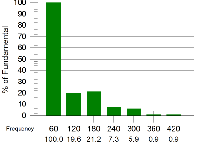
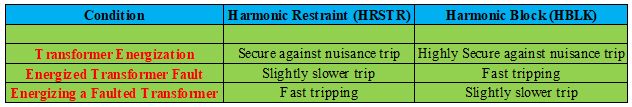
HRSTR: Transformer energization inrush can cause false differential current in the relay and could lead to nuisance trip. This is because inrush current appears on the primary current but not on secondary CT. Fortunately this can be detected since inrush current has significant even order harmonics which can be used in the relay logic to restraint the differential element. HARMONIC RESTRAINT element works by restraining the percentage restraint differential element if the ratio of second harmonic and/or fourth harmonic current to fundamental current is greater than PCT2 or PCT4 setting for 10 cycles when the transformer is energized. Instead of using a fixed threshold, the restraint element shifts the slope line up relative to the amount of differential harmonic current measured.
PCT2, PCT4 setting: The default value in the software can be used if desired. Or the harmonic analyzer tool in the relay software can be used to identify the magnitude of second and fourth harmonic during transformer energization. It should be noted that the inrush current and harmonics could vary between different switching events and hence it is advisable to add some tolerance to the setting even if the harmonics are measured.
Assume the slope line equation as y=mx+b where ‘y’ is the operate current (IOP), ‘m’ is the slope (Slope1 or Slope2), x is the restraint current (IRT) and ‘b’ is the harmonic component. Under normal circumstances there is no harmonic content and the line goes through origin. When there is harmonic content it simply raises the line by ‘b’ keeping the slope same. This is illustrated in the figure below.
If this setting is active, the relay measures the ratio of second and/or fourth harmonic current to fundamental current and if the ratio is greater than PCT2 or PCT4 setting then the relay operation is restrained as shown on the graph above.
HBLK: The purpose of this HARMONIC BLOCK element is to block the percentage restraint differential element if the ratio of fifth harmonic to fundamental current is greater than PCT5. This functionality is useful when the transformer being protected can be ‘over fluxed’ i.e the ratio of voltage to frequency (V/Hz) applied to the transformer terminals exceeds 1.05 pu at full load or 1.1 pu at no load. Unit-generator step up transformers at power plants that can experience frequency variation during startup which could lead to overexciting and overfluxing of transformers. HBLK can be used effectively in those situations.
PCT5 setting: Analysis of transformer currents during overexcitation indicates that 35% fifth harmonic setting is adequate to block percentage differential element. This can be adjusted if needed.
It is possible to enable both these in SEL relay which provides optimum operating speed and security. If the application involves load that produces significant 5th harmonic current, then additional review of HBLK setting is recommended to ensure protection is not compromised.
ICOM: Internal CT compensation. Internal CT compensation is used to compensate for transformer winding induced phase shifts. For example, a delta wye transformer has a 30-degree phase angle difference between primary and secondary. Whether the delta leads wye or wye leads delta depends on the type of delta closing and is discussed in this article. Additionally, CTs could be connected in delta or wye which also could introduce phase angle errors. Internal phase angle compensation in modern digital relays compensates for phase angle errors in 30-degree increments. A full 360-degree compensation can also remove zero sequence components from winding current without introducing any phase angle change. All other non-zero compensation settings also remove zero sequence components from the winding current.
Transformer Differential Protection Example
Let’s consider an example transformer differential protection system with SEL 387/587 relays. For 787 relay the calculations will be similar except for restraint current calculation. Restraint current calculation in 387/587 uses average of winding currents whereas the 787 the calculation is straight addition. This is discussed earlier in this article.
Assume a delta-delta connected transformer with wye connected CT. This means there is no transformer or CT induced phase shift. Assume a ABC phase rotation. ‘R’ refers to restraint coil and ‘O’ refers to operate coil.
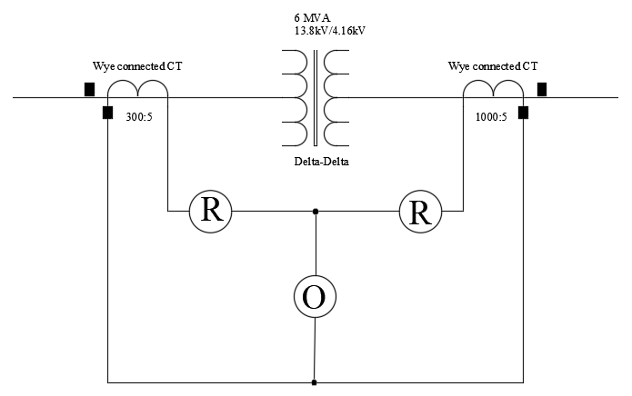
Note the CT polarity connection. Assume rated full load current in primary and secondary.
The tap values can be calculated per the following equation:
Case1: Consider a transformer differential protection scheme with a FULLY LOADED transformer.
Let the winding currents on CT secondary be as follows for normal full load current draw from the transformer. Due to the polarity direction of CT, the ratio currents will be 180 degrees out of phase from primary to secondary as shown below.

Calculate the operate current (IOP) by vector addition and restraint current (IRT) using magnitude addition and divide by 2. For A phase currents,
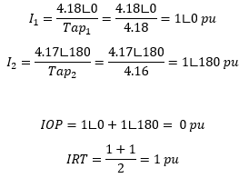
Note that on the percentage restraint differential graph, the coordinates are plotted as (IRT, IOP) on the (x,y) plane. If we plot (1,0) the graph looks as shown below. The IRT, IOP calculate for B and C phases will be similar. Summarizing:

Note that (IRT,IOP) location in the graph is below the tripping characteristic curve and hence no tripping will occur (as expected). Elements 87R1, 87R2, 87R3 which are the differential tripping elements will not be asserted in this case.
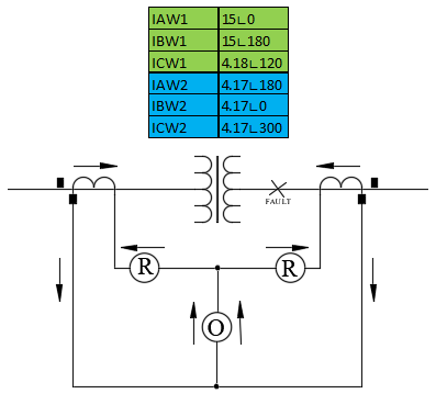
Case2: Consider a transformer differential scheme with an INTERNAL FAULT.
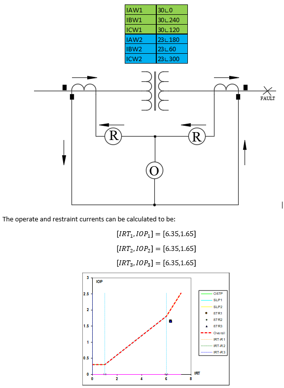
Assume the secondary circuit is fully loaded while there is internal fault with the current magnitudes shown below. Due to internal fault, the primary current will be high, but not the secondary current.
Let’s calculate the operate current (IOP) by vector addition and restraint current (IRT) using magnitude addition and divide by 2.
Convert the current in per unit of corresponding TAP value:

Note that two of the (IRT,IOP) locations in the graph are above the tripping characteristic curve and hence tripping will occur (as expected). Elements 87R1, 87R2 will be asserted in this case. Element 87R3 will not be asserted as it is below the trip curve.
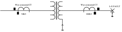
Case3: Consider a transformer differential scheme with an EXTERNAL FAULT. Assume the secondary CT saturate and hence there is a reduction in the magnitude of secondary ratio current produced by CT. Assume no change in phase angles due to saturation. The CT secondary currents are provided below.
Note that (IRT, IOP) location in the graph is below the tripping characteristic curve and hence no tripping will occur (as it should be). Elements 87R1, 87R2, 87R3 will not be asserted in this case. However, this example illustrates the problem when CT gets saturated during a high magnitude external short circuit fault. As can be seen in this example, the trip point came close to the curve. This is the reason for setting slope 1 and slope 2 to avoid nuisance tripping from CT saturation. This example illustrates the benefit of having dual slope operate curve to prevent nuisance trip due to CT saturation.
Transformer Differential Protection CT Connection
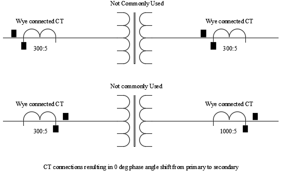
Typically star or wye connected CTs are used for differential protection using digital relays which can be wired in four different ways as shown in figures below. It is preferred that the CT polarity face away from the differential protected zone. That means the source side CT polarity faces the source and the load side CT polarity faces the load. See the figure below for ‘preferred connection-commonly used’. The next preferred connection shown is also acceptable. These connections result in 180-degree phase angle difference between primary and secondary CT ratio currents. The advantage of this connection is that under normal loading conditions, the per unit winding currents which is also called operate current in the relay add to zero since the currents are 180 degrees out of phase.
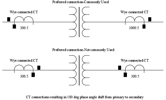
Next possible way of connecting the CT is by having both CTs face source or both CTs face load. These connections are not preferred though it can still be made to work using modern digital relays. Appropriate compensation need to the winding current need to be provided if these connections are used. There will not be any phase angle difference between primary and secondary CT ratio currents.
With modern digital relays any type of CT connections can be ‘compensated’ in the software. If it is possible during the design stage, one of the ‘preferred connections’ using wye connected CT may be selected.
In previous generation applications using electromechanical relays it is common to see delta connected CT on the wye (star) side of the transformer and wye connected CT on the delta side to compensate for the transformer phase shift. In today’s modern digital relays, the phase shift can be adjusted in the software. However older retrofit applications involving delta connected CT do occur and it is necessary to understand the delta connected CT and its nuances.
Delta Connected CT
If a set of CT is connected it delta, then couple of things need to be kept in mind. The CT itself can be wired in ‘DAB’ or ‘DAC’ configuration. What is DAB and DAC?, click HERE? It is nothing but the way the winding is internally connected. See the figure below which is self-explanatory.
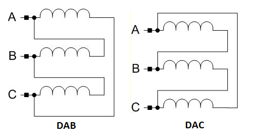
In DAB connection the polarity end of A phase is connected to non-polarity end of phase B.
In DAC connection the polarity end of A phase is connected to non-polarity end of phase C.
In a delta wye transformer, if the delta closing is of type ‘DAB’ then delta side will lead the wye side by 300. If the delta closing is of type ‘DAC’ then wye side will lead the delta side by 300 .
In addition, it has to be kept in mind that delta connected CT produces sqrt (3) times the current produced by wye (star) connected CT. This magnitude compensation can be easily done using software settings in modern digital relays. Additional information of wye and delta connections and its phase angle properties can be found by clicking here.
Differential Relay Application Considerations
A variety of application considerations will have to be taken in to account while applying differential protection. Some of these are:
The phase shift of the current (if applicable) from primary to secondary needs to be accounted for in the current calculation. As an example, if the transformer primary is delta connected and the secondary is star (wye) connected, then the CT ratio currents from primary and secondary will be phase shifted by 300. This phase error will result in a net operate current for the relay and hence could misoperate. There are ways to avoid this which are:
- Use a wye connected CT on the delta side of transformer and delta connected CT on the wye side of transformer.
- For digital relays, it is possible to configure the software to provide the desired ‘compensation’ for the currents to account for the different primary and secondary winding connections/phase shifts.
Effect of magnetizing inrush during transformer energization. The initial energization of transformer will result in large magnetizing inrush current which could appear as inrush current if not compensated. Modern relays use harmonic sensing to detect transformer energization. During the energization period the differential protection could be de-sensitized.
Possible occurrence of overfluxing. Possible nuisance tripping due to overfluxing can be avoided by using fifth harmonic restraint available in modern digital relays.
Zero Sequence Current: It is necessary to provide some form of zero sequence filtering when a transformer winding can pass zero sequence current to an external ground fault. An example of this would be a delta wye-grounded transformer. The wye grounded side of the transformer can have phase to ground faults external to the zone of protection that can create zero sequence current in the measured CT ratio currents. Since the fault is external to the zone of protection it is necessary to remove the zero-sequence current. Older schemes use delta connected CT on the wye (star) side winding to remove zero sequence currents. Modern digital relays can accomplish this using software based compensation.
Ratio Correction: Since primary and secondary CT ratio may not exactly match the transformer rated winding currents or the CT could be connected in star (wye) or delta fashion, some ratio correction will usually be required. For modern digital relays this correction factor is calculated automatically and applied.
Error Compensation: The relay selected need to compensate for steady state, proportional and transient errors in the CT ratio current. Steady state errors are the errors that do not vary with loading. Example is transformer magnetizing current. Proportional error varies with loading such as CT ratio error, error due to tap changing. Transient errors result from CT saturation due to high current flow during a short circuit event.
Tap changing transformers: If tap changing transformer is involved, CT ratios and correction factors are chosen to achieve current balance at the mid tap of the transformer. It is necessary to ensure that current mismatch due to off-nominal tap operation will not cause spurious operation.
CT Remanence
Sympathetic inrush
Also Read: Current Transformer Saturation , Wye and Delta Transformer Connections, Transformer Connections: Phase Shift and Polarity