Phase shift and phase polarity between two windings of a single-phase transformer depends on how the windings are wound on the core. Transformer phase shift and transformer polarity needs to be considered for many applications some of which are:
- Forming a 3-phase transformer using single phase transformers
- Parallel operation of transformers
- Voltage transformer connections for metering
- Voltage transformers for synchronism check between two sources, protection etc.
In this article basics of transformer polarity is discussed. A method to test potential transformer polarity (PT or VT) is discussed and actual test results provided.
![]()
Transformer Phase Shift
There are four different ways in which single phase transformers can be connected to form three phase banks. These are:
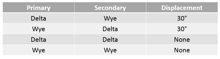
Wye-Wye and Delta-Delta transformers do not cause any phase shift from primary to secondary. Delta-Wye transformers have a 30-degree phase shift which is discussed below.
Delta Wye or Wye Delta Transformer Phase Shift
We know that across a delta-wye (star) or wye- delta transformer there will a 30-degree phase shift between line voltages. With this there are two options: delta could lead the wye side by 30 degree or wye side could lead the delta by 30 degrees.
What determines transformer phase shift and which side of delta-wye transformer leads or lags?
Answer: The way the delta is ‘closed’ determines which side leads or lags. There are two possible combinations which are discussed below:
- Delta Closing- Type DAB
This is one method of closing the delta triangle. In this connection, the polarity side of A phase is connected to the non-polarity side of B phase. Three phase transformer connection diagram using this method is shown below.
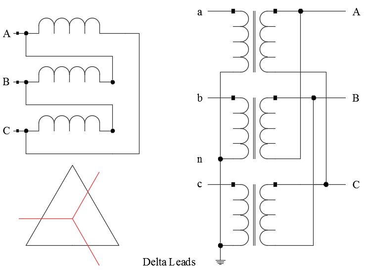
Delta Closing- Type DAB
The figure above shows a delta wye connection with ‘DAB’ connection. In this case delta side will lead the wye side by 300. This is the normal connection for delta wye transformer with delta on the primary. Per north American standards the primary side leads the secondary low voltage side by 300.
2) Delta Closing- Type DAC
This is another method of closing the delta triangle. In this the polarity side of A phase is connected to the non-polarity side of C phase. Three phase transformer connection diagram using this method is shown below.
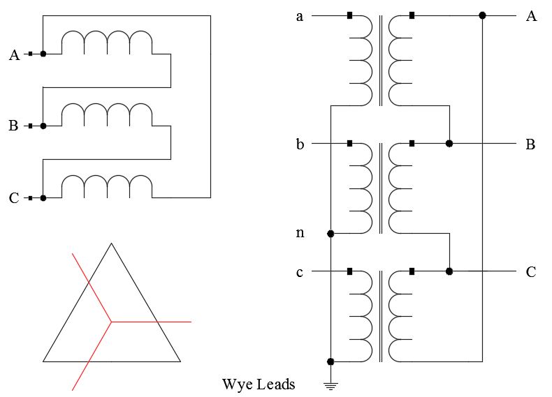
Delta Closing- Type DAC
The figure above shows a delta wye connection with ‘DAC’ connection. In this case delta side will lag the wye side by 300. Or in other words the wye side will lead the delta side by 300. This is the normal connection for wye delta transformer with wye on the primary.
Note that these phase angles are referring to positive sequence voltages. A method to derive the polarity by looking at winding connections is given in ref [1].
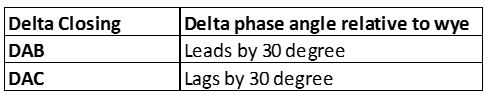
DAB vs DAC Delta Connection
Transformer Polarity
There are two polarity standards for transformers. These are subtractive and additive as shown below. Polarity markings are indicated by ‘X’.
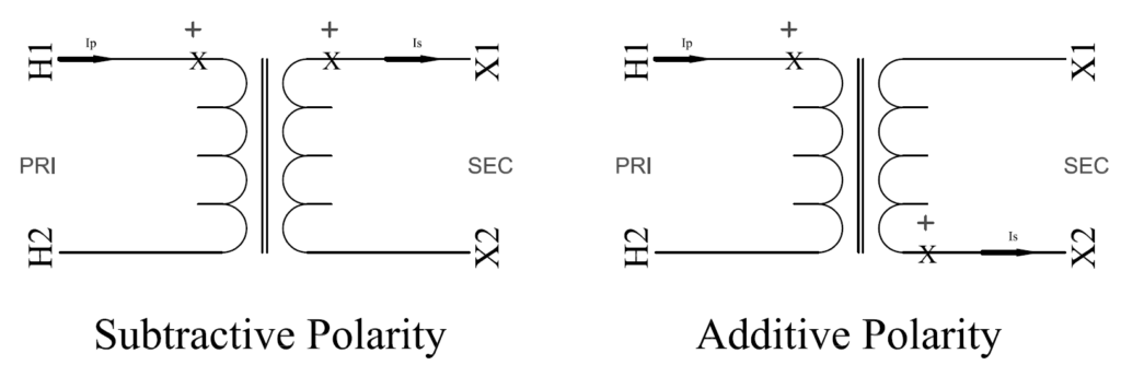
Single phase power transformers (in North America) could be additive or subtractive depending on the kVA and the voltage class. Other regions of the world too could have a mix of additive and subtractive polarity transformer in use. Two rules of transformer polarity are:
- Current flowing ‘in to’ polarity marking of one winding flows ‘out of’ the polarity mark of the other winding. Both currents will be in phase.
- Voltage drop from polarity to non-polarity across one winding is essentially in phase with the voltage drop from polarity to non-polarity across the other winding.
Additive Polarity: For power distribution transformers that fall in to the category as noted in the IEEE standard below has additive polarity. These are mostly single-phase distribution transformers.
IEEE Std C57.12.00-2000 Standard for liquid immersed distribution, power and regulating transformers states that “Single phase transformers in sizes of 200kVA and below and having high-voltage rating of 8,660V and below (winding voltage) shall have additive polarity. All other single-phase transformers shall have subtractive polarity”.
Subtractive Polarity: Large power transformers and instrument transformers usually have subtractive polarity.
Polarity marking is indicated by a dot or ‘X’ or it can be indicated by standardized terminal markings. Below is another way of indicating transformer polarity. The secondary polarity is determined by the location of ‘X1’ relative to ‘H1’. If H1 and X1 are on the same side then the transformer has subtractive polarity and vice versa.
Here is an instrument transformer with subtractive polarity. Note that in addition to having a white ‘dot’ indicating the polarity, it also has H1 and X1 markings. The schematic for this VT or PT will be the same as the figure shown above for subtractive polarity.

Potential Transformer [Square D]
How to check polarity of a transformer?
Sometimes it is required to test the polarity of a single-phase transformer or a voltage transformer (VT or PT) for testing or troubleshooting purposes. One way to test the VT with known voltage transformation ratio is to connect an AC source as shown in the figure below.
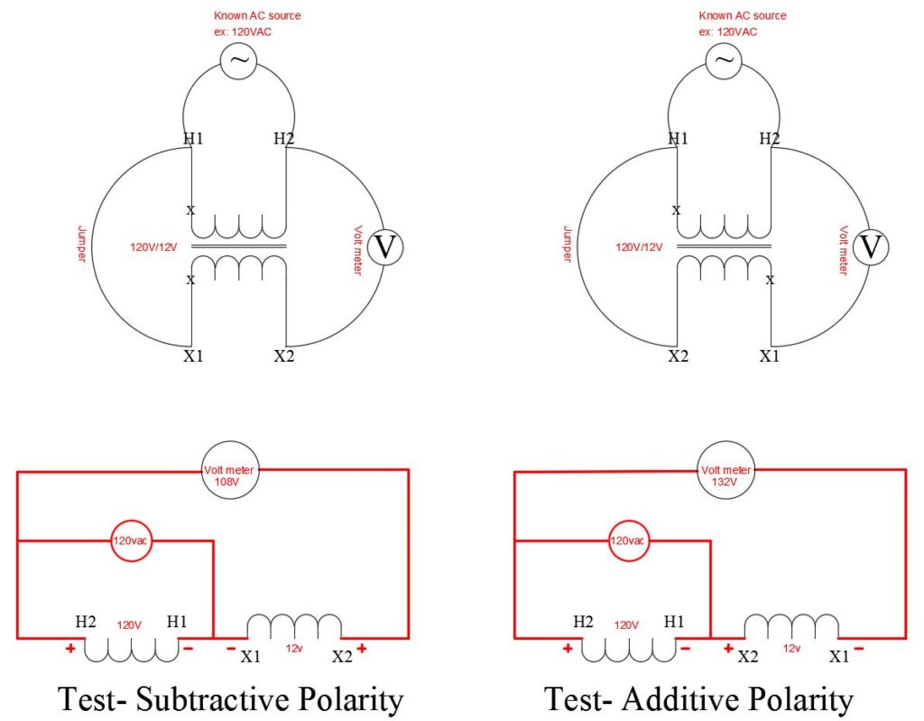
Testing Transformer/PT Polarity Schematic (top) Simplified Test Circuit (bottom)
Note: Care should be taken in connecting the voltage as dangerous voltage could appear depending on the voltage rating and the terminals at which connections are made. Connection at 120VAC or smaller to be applied at the high voltage terminals and not at low voltage terminals.
In the figure above +, – are for illustration purposes identifying the terminals at same potential at any given time and do not represent DC voltage.
For additive and subtractive polarity winding, terminals H1 and X1 will always be at the same polarity. This knowledge will help create the figure above. In the example test above, the transformer ratio is 120V/12V. If the Voltage Transformer (VT) has additive polarity then 132V will be read on the multimeter. If the VT has subtractive polarity then 108V will be read on the multimeter.
Voltage Transformer Polarity Testing
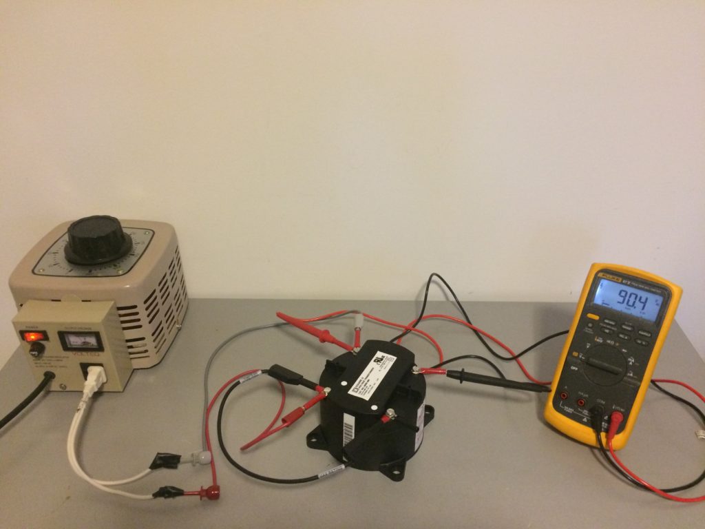
Below is the test set up for testing a Voltage Transformer or Potential Transformer polarity testing. The test leads are connected as detailed in the section above. The specs of the VT are:
Primary 480V
Secondary 120V
Transformation Ratio= 480/120= 4
H1 and X1 are on the same side of the transformer (similar to the picture of the VT shown above). Hence the VT is of subtractive polarity. After making connections as shown in the schematic above. The voltage across H2 and X2 is measured to be 90V.
This confirms the polarity of VT is subtractive. The voltage applied across H1 H2 is 120V. Based on the transformation ratio 120/4=30V will be induced across X1 X2. Since the windings are connected for subtractive polarity, the net voltage measured across H2 X2 is 120-30=90V. This is exactly what is measured.
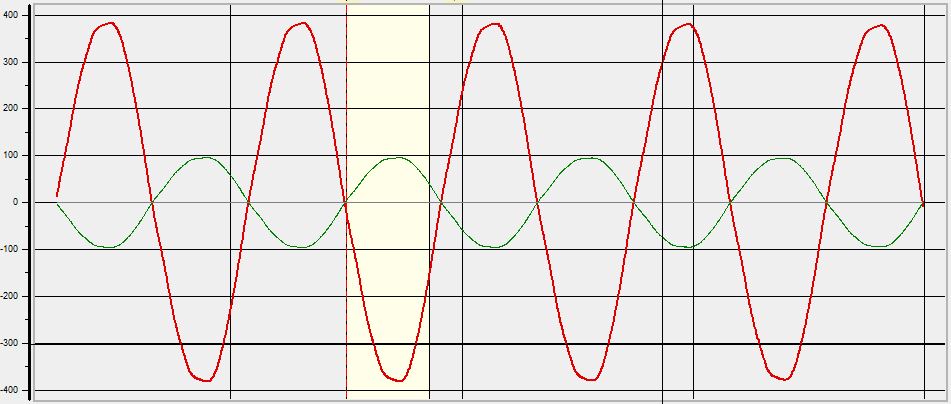
Voltage waveforms from primary and secondary are shown below. For subtractive polarity the voltage waveforms across H1 H2 and X1 X2 has same phase angle. In other words the potential of H1 and X1 rise and fall in unison.
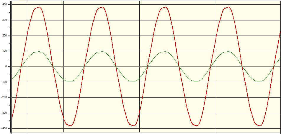
For additive polarity the voltage waveforms across H1 H2 and X1 X2 has phase angle difference of 180 degree.
Additional reading:
Phase Sequence and Phase Angle
Current Transformer Saturation
Ref [1]: Power System Analysis and Design J Duncan Glover, S. Sarma, Thomas Overbye