Phase rotation or phase sequence is a concept that is not well understood and misapplied in many installations. Lets dive in to what is this ‘Phase Rotation’ as is referred to in 3 phase electrical systems. Here are the some keys points to note:
Phase rotation/ Phase Sequence is important in the following applications
For 3-phase motors that are directly connected to the AC supply.
For 3-phase motors that are directly connected to the AC supply through a softstarter.
Certain types of older electromechanical protective relays
Certain older electromechanical power meters.
Paralleling a 3 phase AC source with a 3-phase generator.
Connecting one ac source#1 to another ac source#2- like paralleling two transformers.
Phase rotation/ Phase Sequence is not important in the following applications
Where 3-phase motor is fed by a Variable Frequency Drive (VFD). In this case, the VFD input section does not care about the phase sequence. The phasor sequence on the output of the drive can be modified by the program settings on the VFD and is usually selectable as clockwise sequence or anti-clockwise sequence.
Connecting to a transformer.
Connecting to any type of rectifier type loads.
Newer electronic solid state relays. These relays can be programmed to have either A-B-C or A-C-B sequence.
Single phase motors.
What is phase sequence?
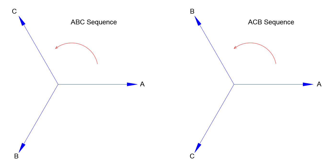
The three phases of an AC source is usually referred to as A-B-C, U-V-W, a-b-c, R-S-T or simply 1-2-3 with the usage varying over different countries and geographical areas. Irrespective of the notation, phase rotation or phase sequence indicates the sequence at which each phase reaches its peak voltage. For us to understand this correctly one key thing to remember is that -ALL THREE PHASE AC VECTORS ROTATE COUNTERCLOCKWISE at the system frequency. The vector phase diagram that we see on text books represent what would be seen under a light that switches on and off at the system frequency. That means at every 16.6ms (for 60Hz system), the vector would rotate and come back at the original position and hence appears static to the viewer.
Phase sequence and not phase rotation is the term defined in IEEE dictionary (IEEE 100-1984). However both terms are used extensively over the years.
Why choose any other phase sequence other than A-B-C?
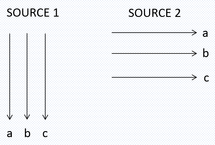
It should be noted that the specific phase sequence is only a name designation that was established in the early history of an electric utility company and it becomes difficult to change after many years of operation. Some electric utilities operate with A-B-C sequence while other operate with A-C-B sequence. Some companies use one phase sequence at one voltage and another at a different voltage. To illustrate how different phase sequence can originate, lets look at the following picture:
Assume two sources, these could be two electric utilities or generators, one is called source 1 and other source 2. Early on, the engineers for source 1 and 2 decided to name the three phases as shown in the figure below.
Now do you think interconnecting these two sources will be a problem?
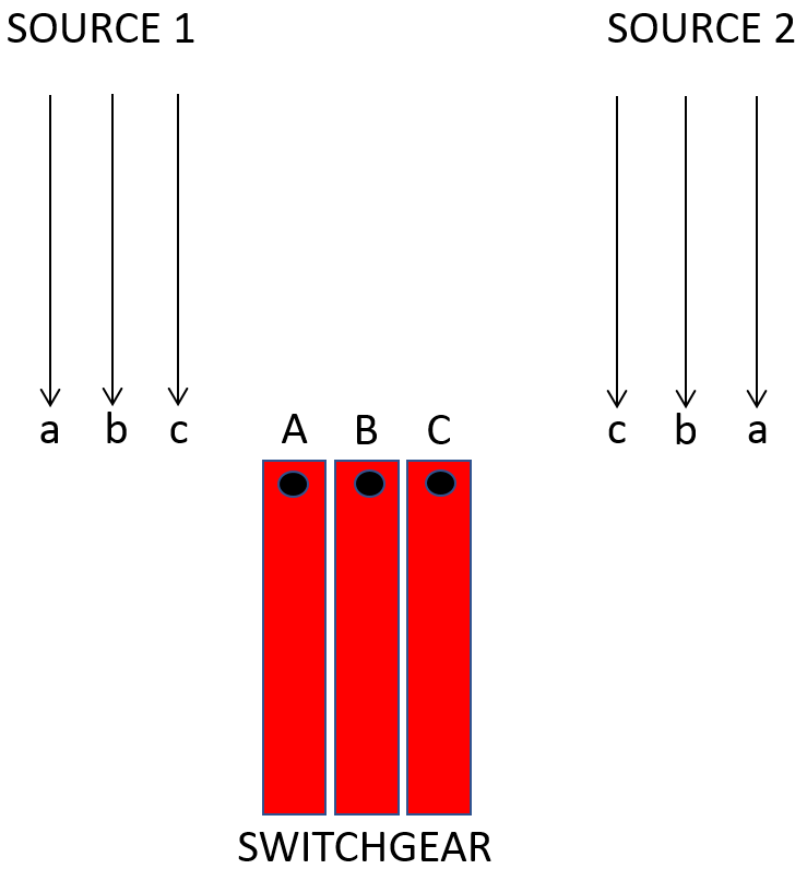
For us to understand why issues arise when trying to interconnect these two system we should have some background in the switchgear construction. Switchgears / switchboards/ panelboards are constructed with consistent phase relationships. Standards such as IEEE C37.20.2 , IEEE C37.20.2, IEEE C37.20.3 all require that the bus conductors be arranged 1-2-3 OR A-B-C from left to right, top to bottom, front to back.
When trying to connect an inconsistent phase sequence (between different sources) with switchgear which always have consistent set of phase marking, we can see that at least two lead wires of the source which has other than A-B-C sequence needs to be changed.
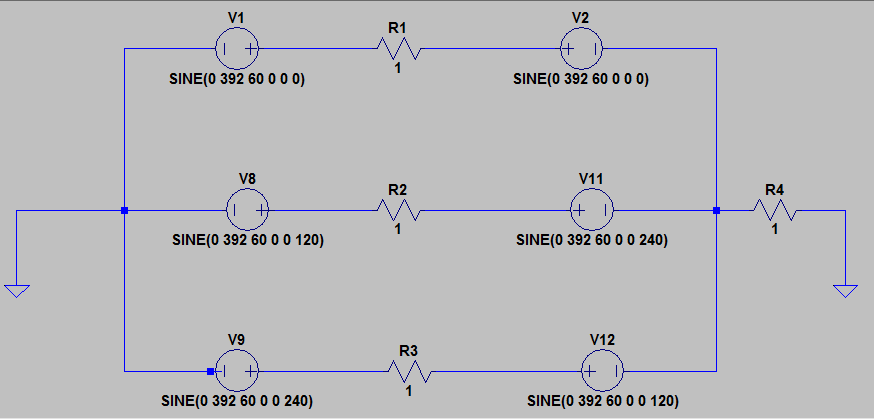
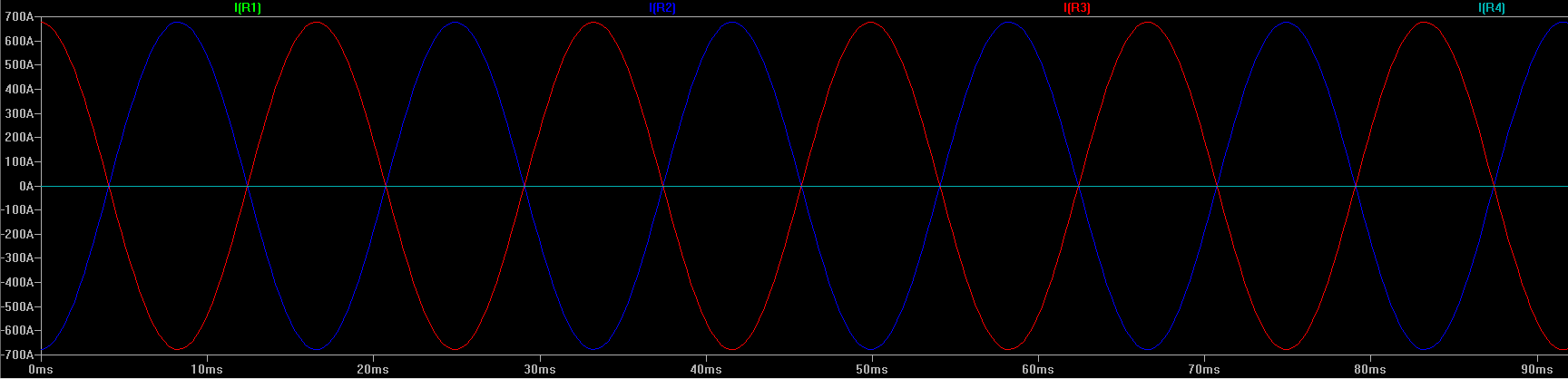
To illustrate the consequence of interconnecting a system with A-B-C sequence with another system with A-C-B sequence, a simulation can be performed using ideal sources. The simulation results are given below. As can be observed high levels of short circuit current flows between the two sources which will usually result in protective devices for the respective sources tripping and/or equipment damage.
In this case over 700A of current flows between the two sources. Note that the current is entirely in the phase circuits and no neutral current flows.
Phase angle
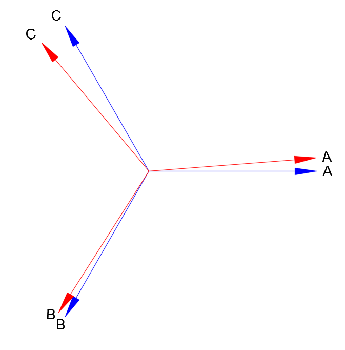
Another situation that usually occurs is when we have two sources with similar phase sequence or phase rotation, but the phase angles are not exactly the same. See the figure below to understand this better. As can be observed both sources have ABC rotation (remember phasors always rotate counter clockwise), but one source angle is not exactly 0, 120, 240 degrees as one would expect. This could be caused due to a variety of reasons some of which are:
The utility source voltage may not have ideal phase angle displacement.
There could be upstream transformers that could be causing some phase angle difference due to the construction of the transformer. Remember wye-wye transformers ideally should not introduce any phase angle difference between primary and secondary.
If one source has a delta-wye transformer upstream, it will cause a 30 degree phase angle difference compared to the source that does not have any upstream transformer .
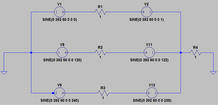
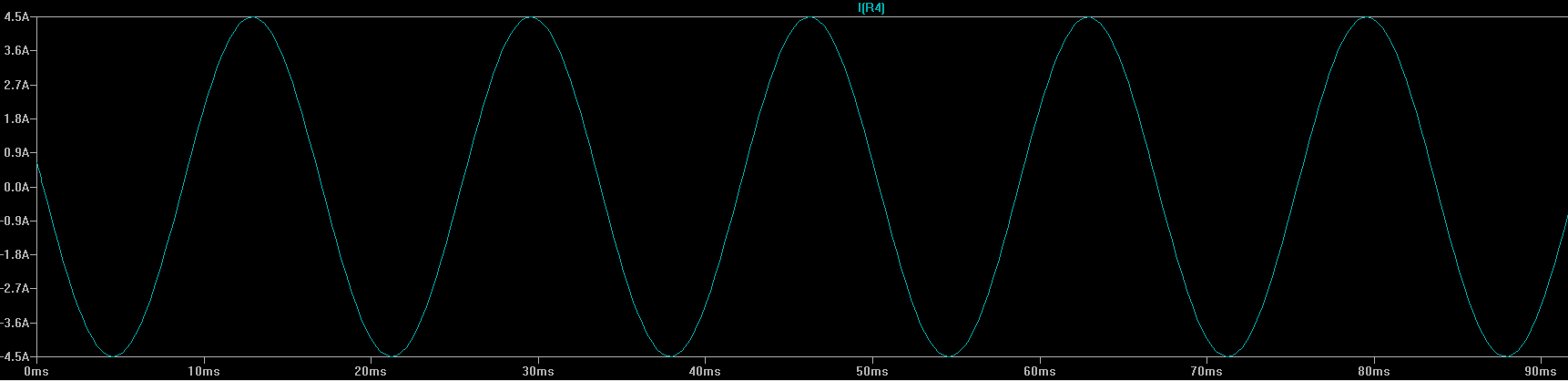
The question usually is whether I can connect the two systems or not. When connecting two systems with slightly different phase angles, there will be net neutral current that would flow in the ground/neutral that interconnects the two sources. This is illustrated in the simulation below. It can be seen that two sources have similar phase sequence, but source 1 has 0,120,240 degree whereas source 2 has 1,122,239 degree phase angle.
Interconnecting two sources with slightly different phase angles will result in neutral/ground current circulating between the two sources.
An application where both phase sequence and phase angle is important–Paralleling two transformers in a low voltage substation.
Often times it is desired to close the tie breaker and parallel the two medium voltage transformers for meeting the load requirement or some other requirements. Two things need to be performed (in the order) pertaining to phase sequence to make sure things work as intended.
Check Phase Sequence:Using phase sequence meter , ascertain that the two sources have similar phase sequence, either both having ABC sequence or both having ACB sequence.
Check Phase Angle: Measure the potential difference between the respective phases that is going to be paralleled. The magnitude of the potential difference between the corresponding phase will indicate the phase angle difference between the two sources. Ideally no potential difference should exist between say phase A of source 1 and phase A of source B if both sources have phases that are exactly at 0, 120, 240 degrees apart. Minor phase angle differences can usually be tolerated and it will only result in circulating ground current between the transformers. This test can also be done by using an oscilloscope. If large phase angle difference is noticed additional engineering need to be performed prior to paralleling two transformers.
Possible consequences of not checking the phase sequence while connecting devices:
Motors could rotate in the opposite direction and depending on the driven load it can damage the driven load.
Electromechanical relays could nuisance trip or worst not function at all.
Electromechanical power meters could give erroneous reading.
Dangerous short circuit current can flow while interconnecting sources with different phase rotation/sequence.
Possible consequences of not checking the phase angle while connecting devices:
Circulating phase current between the two sources which could result in overheated transformers.
Circulating ground currents between the two sources.
Circulating ground currents causing nuisance trip on ground fault relays.