This article discusses the medium voltage (MV) or High Voltage (HV) cable shield grounding or termination methods. Why do high voltage cables have shields? Shielding of electric power cable results in symmetric electric field distribution within the cable insulation and prevents stress damage. Refer to ‘Medium voltage cable construction’ for additional details on cable shield and its uses. Proper routing of shielded cable when applied with zero sequence ground fault CT is also discussed in this article.
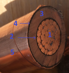
The various layers of a high voltage cable from inside-out are:
1)Conductor
2)Conductor Shield
3)Insulation
4)Insulation Shield
5)Outer Shield
6)Outer Jacket (Not shown in the picture)
More details about the cable construction is available here.
Outer Shield, screens, armor for Medium voltage (MV) or High Voltage (HV / HT) cables need to be connected to ground / earth in some manner. Grounding / earthing of shielded cable can be done in two ways:
Single point grounding
Multiple point grounding
Single Point Grounding
Single point grounding refers to the practice of connecting the cable shield to ground only at one point. This is also referred to as open circuit shield. Here are the advantages and disadvantages of single point grounding:
Advantages:
*Since shield is only grounded at one point, no closed circuit exists and hence no induced shield currents can flow. Small eddy currents will still circulate within the shield but that is not part of this discussion.
*Since there is no shield current, derating of cable ampacity is not required.
*Shield is useful in providing protection against capacitively induced noise. This may not be of concern at power system voltages.
Disadvantages
*Since the shield is only grounded at one location, shield current cannot flow. This results in voltage across the open circuit portion of the shield with maximum voltage appearing at the end that is farthest away from grounded point. IEEE standard 575 limit this voltage to 25V and less.
*Single point grounded shield is not useful in providing protection against inductively induced noise. This may not be a concern at power system voltages.
Table below illustrates single conductor cable length with shield grounded only at one point to limit shield voltage to 25V.
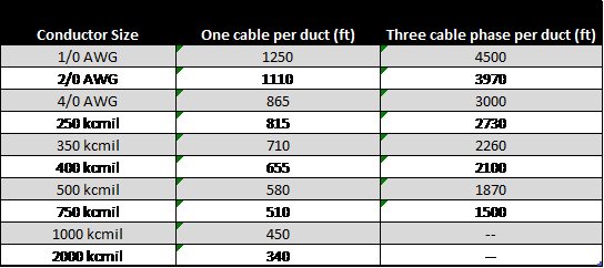
Link for AWG to mm2 converter CLICK HERE.
When cables are operating with less than full load, the lengths could be longer.
Multiple Point Grounding
Multiple point grounding refers to the practice of connecting the cable shield to ground at multiple readily accessible locations with minimum of 2 connections. This is also referred to as closed or short circuit shield. Here are the advantages and disadvantages of multiple point grounding:
Advantages:
*Since shield is connected to ground at both ends, no shield voltage can exist. Hence this connection increases safety.
*Shield provides protection against both capacitively and inductively induced noise.
Disadvantages:
*Since shield is connected to ground at both ends, current is induced in the shield that has a closed path now. This current varies with the loading on the main cable and results in additional cable heating. Derating of the cable ampacity is usually required.
Refer to IEEE Std 575 for details on different types of multi grounded systems.
How does open circuit shield voltage appear on single point grounded cables?
Shield voltage is electromagnetically induced by the main conductor on the shield. Since there is no closed path in single point grounded shield, the voltage appears on the ‘non-grounded’ end of the shield. This voltage is not constant and depends on various cable parameters.
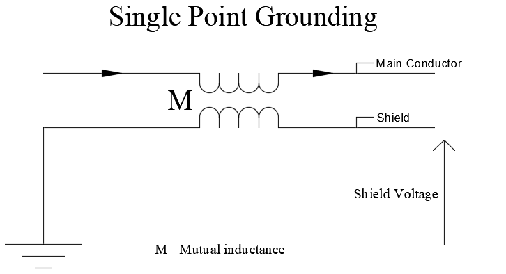
The voltage that is induced in the shield depends on:
1)Mutual inductance between main conductor and shield
2)Current in the main conductor
3)Distance to the grounded point
Shield voltage is limited by standards to below 25V. If the shield voltage gets higher then it may lead to electric discharge and create unsafe conditions.
How does circulating current flow in multiple point grounded cables?
It is should be noted that the cable shield current for multiple point grounded shielded cable is not constant. The shield current is electromagnetically induced on the shield and varies based on the load current on the cable main conductor.
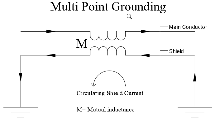
The current that is induced in the shield depends on:
1)Mutual inductance between main conductor and shield
2)Current in the main conductor
3)Resistance of the shield
The circulating shield current does not depend on the length of cable or the number of shield to ground connections (minimum two connections needed for multi grounded shield). This is because when the conductor length increases the magnitude of sheath induced voltage also increases along with the value of electrical impedance.
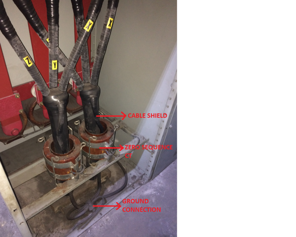
Shield Routing through Zero Sequence Current Transformer
When terminating medium voltage cables in to a switchgear with zero sequence CT (core balance CT), the cable shield needs to be routed as discussed below for ground fault relay to operate properly. The following should be noted:
*The stress cone termination needs to be done between the zero sequence CT and the cable lugs.
*The shield wire needs to be routed back through the zero sequence CT and terminated to ground bus on the other (load) side of CT.
*Between stress cone termination and the final ground connection, the shield wire should not contact any other grounded structure (either enclosure or other ground connection).
*Incoming metallic conduit must be connected to the switchgear ground bus on the load side of zero sequence CT. The incoming metallic conduit ground need not be routed through the zero sequence CT.
Additional Reading: Medium voltage cable construction, Neutral Inversion and Neutral Displacement, AC voltage drop and system power factor