Saturation of current transformers (CT) when carrying high magnitude current is a well-known phenomenon. Usually symmetrical fault current is used to size CT using ANSI C rating. However, DC component of the fault current has much more influence in producing severe saturation than symmetrical fault current. CT applied near large generating stations or otherwise installed in location with high X/R are susceptible to delayed and long-lasting saturation due to decaying DC component. Differential relays are susceptible to nuisance tripping if CT on either side of protected device saturate at different times. This article goes through basics of DC current saturation.
Current Transformer Saturation
DC current arises during a fault event due to two reasons:
- Current in an inductive circuit cannot change instantaneously.
- Steady state current before and after fault must lead or lag voltage by system power factor.
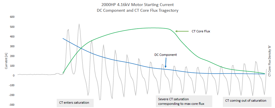
DC component of CT primary current requires substantially greater CT core flux than steady state sinusoidal AC current. This can be seen in fig 1 below. DC flux in the CT core causes CT to enter into saturation at each peak of current wave. CTs that are saturated heavily produces a ‘shark fin’ shaped secondary current. Figure 1 shows a heavily saturated CT waveform experienced during a large motor starting event.
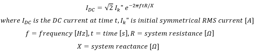
Magnitude of DC component and decay rate of DC is determined by system X/R ratio. Near a generating station X/R will be high (say 40) whereas in low voltage applications X/R will be lower (say 10). This means fault near to generator will take longer to settle to steady state value and CT is much more vulnerable to saturation. For a simple power system with resistance and reactance, magnitude of decaying DC component after a short circuit can be calculated using the formula below:
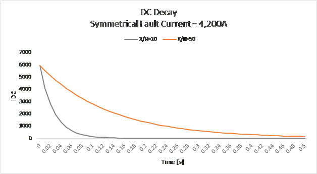
When fault occurs on a system with large X/R, DC component of fault can sustain for a long time compared to a system with lower X/R ratio. As an example, graph below shows the DC decay during a 4,200A symmetrical fault current event for X/R of 10 and 50.
Long DC decay can drive CT into saturation as DC component requires substantially greater flux than that needed to satisfy the AC component.
DC component of fault current will not cause CT saturation if the following criteria is satisfied [1].
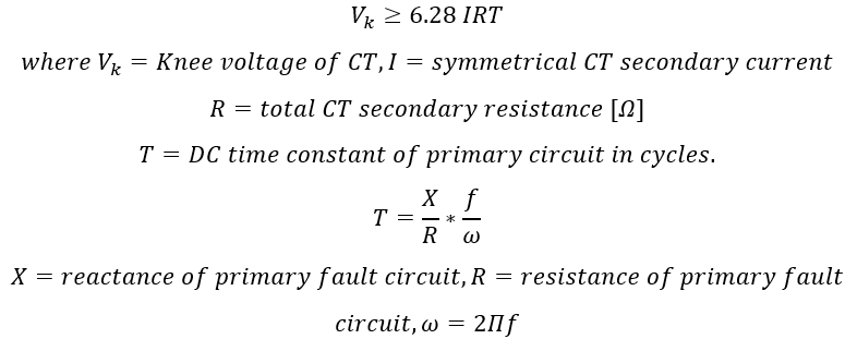
For example, consider a circuit with 20,000A of fault current and X/R of 10. Assume CT ratio is 600:5 and burden resistance R of 1.5Ω. Using the above equation, to avoid DC saturation the CT knee voltage has to be above 159V.
Note remanence is not factored in the equation above. Remanence will make CT saturate faster and some remanence is usually present in all CT that are in operation.
Time to Saturate
Consideration of DC saturation of current transformer is very important in differential relaying applications. Under ideal conditions when there is an external fault [outside the protected zone], net differential current should be zero. However, when one or more CT enters saturation at different times then a net differential current result which could cause differential relays to operate. An important parameter to consider is time to saturate.
Time to saturate for a CT is given by [2]:
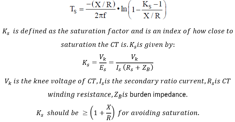
Consider a generator differential application as shown in fig 3. Maximum external fault current is 4.2kA at 13.8kV. Time to saturate is calculated with varying X/R ratio and varying load burden. These are shown in figure 4.
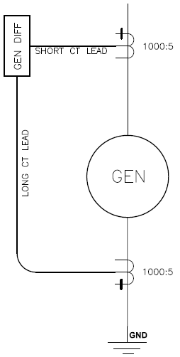
In figure 4 second graph (right) illustrates a very important and often overlooked aspect of CT selection. Even if CT on either side of bus or generator differential relays are of same ratio and accuracy class, time to saturate could be significantly different depending on the burden resistance.
For differential relaying applications, one set of CT could be at outdoor yard and second set could be inside the switchgear along with differential relay. Burden for yard CT could be higher than that for CT mounted inside the switchgear. For an external fault, CTs can saturate at different times and a net differential current could flow into the relay and create a trip condition.
An identical scenario could play out in low impedance bus differential protection. One set of CT could be at a distant Main bus and rest of CTs could be in the switchgear along with feeders. Protective relay could be indoors. In this case the Main CT will have larger burden impedance and may saturate faster compared to feeder CTs.
High impedance bus differential relaying do not experience this issue as the CTs are connected to a high resistance inside the relay and they operate on a different parameter [voltage rather than current]. Details on high impedance bus differential relaying can be found in the article below.
Read: High Impedance Bus Differential Relaying
![CT Time to Saturate vs X/R [left] and vs Burden [right]](https://voltage-disturbance.com/wp-content/uploads/2021/05/CT-Time-to-Saturate-vs-X_R-left-and-vs-Burden-right-1024x284.png)
Some options to make time to saturate same on either side of differential relays are:
- Make the burden on each set of CT the same by adding extra length of wire to match CT with longest lead.
- Add burden resistors to equalize resistance on each set of CT. This method has some drawback as this is less reliable. A failure of resistor could lead to open circuit CT.
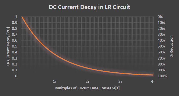
- Delay the tripping by increasing trip time to greater than three DC time constants. In three-time constant (3т), DC component of asymmetric fault current would have reduced by 95%. Refer to graph below which shows current decay in an Inductive-Resistance (LR) circuit. CT needs to be sized for the maximum available symmetrical fault current. After three time constant the current will be back to symmetrical fault current and the CT ratio current will be accurate.
Calculator below can be used to get the system DC time constant (т) for a given X/R ratio and system frequency.
Read: Open circuit current transformer
References:
[1] Protective Relaying Theory and Applications; Walter A Elmore.
[2]: IEEE C37.110-2007, IEEE Guide for the Application of Current Transformers Used for Protective Relaying Purposes.