Open neutral or broken neutral on a service transformer or service cable into a facility can result in serious overvoltage or undervoltage. Relative magnitude of loads on each phase and return path resistance determines which phase experience over voltage or undervoltage.
Open neutral can result in equipment malfunction, damage, overheat and possibly fire. Open neutral issues discussed in this article can happen in single or three phase distribution system though it more commonly experienced in single phase systems.
Open neutral occurs much more frequently than most people would think. Storm, accidental disconnection, theft, rust or damage etc. can result in neutral wire at the service transformer to be disconnected from transformer neutral. It is interesting that phase that is lightly loaded will experience overvoltage while the phase that is heavily loaded will experience undervoltage.
There are two conditions to consider for analyzing open neutral based on grounding practice.
- Multi point neutral ground: Where neutral is earthed at both transformer and panel
- Single point neutral ground: Where neutral is earthed at transformer only
Multi point neutral grounded System: In multi grounded systems, open neutral ‘forces’ return current to flow through earth electrode back to service transformer. This ‘earth current’ flows from customer to earth and can take many paths some of which could be through ground-neutral connection of other customers fed from same service.
Current can also flow through CATV shields, metallic water, gas pipes that are typically connected to ground at each customer’s panel. This can cause local or remote ground potential rise (GPR) resulting in stray or tingling voltage on grounded surfaces such as refrigerator handles, control panel enclosure etc. This issue is discussed later in this article.
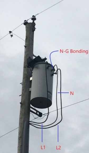
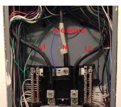
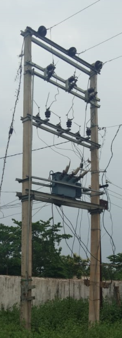
Voltage variation can be explained with the figure 2 below. Transformer neutral is grounded (N-G Bonding) at the transformer (at the pole-see figure 1a) and also at inside by the customer metering point (see figure 1b) or the service entrance panel.
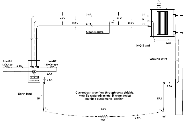
Under normal conditions, the secondary voltage will be 120V between line to neutral and 240V between line-line. Neutral voltage to ground will be 0V. Let’s assume for the example shown that load#1 has resistance of 12Ω, and load#2 has 1200Ω.
Read: Voltage Unbalance
When neutral wire gets accidently disconnected from transformer as shown in figure 2, neutral return current has no choice but flow through physical earth (ground) to reach back to transformer [source]. This ground path between transformer and service entrance panel is typically relatively high resistance path on the order of 10’s or 100’s of ohms. In the example figure we have assumed earth resistance to be 20 Ω.
Under these conditions, voltage drop across load#1 and load#2 can be calculated to be 45V and 195V respectively. Devices connected to phase L1 will experience undervoltage and phase L2 overvoltage.
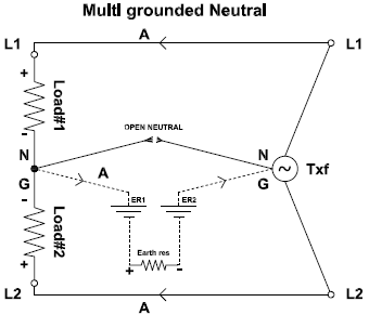
Circuit in figure 2 can be analyzed using the electrical equivalent circuit shown in figure 3.
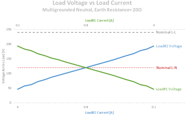
For the example shown with open neutral, if we vary load#1 and load#2, line-neutral voltage will vary as shown in the graph below. As observed, voltage across each phase is unpredictable and will depend on load current on each phase at a given time.
This is the reason customers report random and highly variable voltage during an open neutral condition. Lightly loaded customers will experience increased voltage and heavily loaded circuits (both has to be fed from same transformer) will experience undervoltage.
Open Neutral and Ground Potential Rise
During open neutral condition, return current is forced to flow through ‘earth’. This leads to two things that is of interest:
- Local Ground Potential Rise (GPR)
Current flowing through local earth rod will create local ground potential rise, magnitude of which will depend on current and earth resistance. Say earth resistance is 20Ω and 5A flows which results in 100V of GPR. All the grounded objects (ex. refrigerator) in that customer premise will also be elevated to 100V potential. A person standing on kitchen floor (at earth potential of 0V) touching refrigerator will experience 100V of shock.
- Remote Ground Potential Rise (GPR)
Earth currents can ‘leak’ through ground-neutral connection of neighboring customers. This can cause local ground potential rise (GPR) at a non-faulted customer premise that is fed from the same source transformer. This is manifested as ‘tingling’ voltage or stray voltage when person touches on grounded appliance like refrigerator door handle. Often customer will call an electrician and will not find an issue at his location. Until and unless electric power company finds the location of open neutral and fixes the issue, tingling stray voltage issue will persist.
Read: Voltage Regulation
This is especially a problem in many European or Asian distribution systems where a single distribution transformer powers hundreds of customers. An open neutral on any one customer can cause tingling voltage at many other ‘innocent’ customer locations. Magnitude of tingling voltage will depend on earth resistance at that customer service and amount of ground current.
Read: Voltage Swell
An example of open neutral voltage variation with different values of earth resistance is shown below. Load resistance values used are as shown in figure 2.
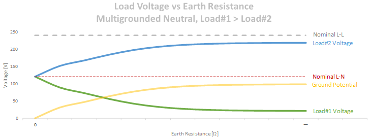
Note that when earth resistance is zero ohm then no voltage variation is seen as expected. This is because earth is functioning as neutral conductor with no resistance.
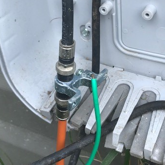
If there are any alternate ground paths like CATV shields, telephone lines, water, gas lines etc. then majority of neutral current will flow through these paths instead of earth. Neutral current will flow through these alternate paths, get to neighbor’s Ground-Neutral bond and back to service transformer.
In the process cable TV shield, telephone wires will likely get damaged. Remember that CATV shields are grounded at each customer and thus is a good parallel path for neutral current, same is the case for metallic water, gas lines and telephone grounds. A severely burned CATV shield is usually is good indication of open neutral. It is not easy to detect and troubleshoot open neutral condition when one transformer feeds multiple customers. Any one of them could be experiencing open neutral.
Single point neutral grounded system: This is not a common practice where neutral is grounded (earthed) only at the transformer however such installations do exist.
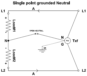
When neutral to customer is open as shown in fig 7, full phase-phase voltage will be applied across series combination of load#1 and load#2 resistance. Relative magnitude of each load resistance will determine load voltage based on voltage divider rule.
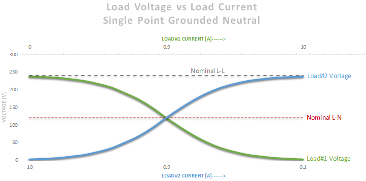
Figure 8 shows the variation of line-neutral voltage as the loads are varied. Voltage across load can reach full phase-phase voltage of 240V in this example. This can easily damage insulation of 120V appliances and can result in damage, fire etc.
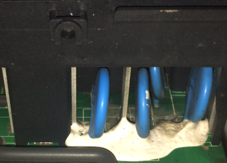
Open Neutral Damages
Over voltage due to open neutral condition can lead to surge arrestor (MOV) failure, insulation failure, transformer overheating and possible fire.
Under voltage due to open neutral condition can lead to air conditioning or refrigeration loads to shut down, motor overheating etc.
Customers can purchase and install automatic voltage protection devices at their service to prevent damages resulting from open neutral condition. These devices should detect an unbalanced voltage condition and open the circuit. When voltage is restored, the circuit should be capable of resetting automatically.