Ground Potential Rise [GPR]
Ground potential Rise (GPR) per IEEE Std 80 is defined as “The maximum electrical potential that a substation grounding grid may attain relative to a distant grounding point assumed to be at the potential of remote earth. This voltage known as GPR is equal to the maximum grid current times the grid resistance”.
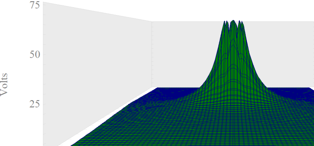
Under normal circumstances the potential of a grounded object will be same as the potential of remote earth (0V). When fault current flows in to ground or flows from ground to object, local ground potential gets elevated. This is because local ground (or earth) has a finite resistance. The flow of ground current into this resistance creates a potential rise relative to a distant point on earth. Ground potential rise simulation graph is shown in figure 1. It can be seen for this example that local ground potential is raised to 75V relative to distant earth.
GPR studies are often carried out to find out the voltage potential gradients around the affected equipment. These equipment could be cellular towers, power substations, transmission towers etc. During a power system fault involving ground (earth), local ground potential relative to remote earth can be elevated significantly (thousands of volts). All the grounded equipment in that location (metallic objects, communication grounds etc.) will also be elevated to this high voltage. A communication cable that runs from this point to a remote location (at 0V) can experience significant current flow due to this potential difference and will often get damaged unless precautions are taken.
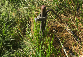
Consider the case of a ground electrode (earth rod) driven 10ft in to ground with a soil resistivity of 25.25 Ωm.
Using the Earth Resistance Calculator, we can calculate that the expected earth resistance for this installation is 8.16Ω. Assume 100A of current is injected in to ground through the ground electrode. The expected GPR in this case will be 100A*8.16Ω=816V.
Earth Resistance Calculator
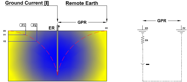
In the figure above the dotted red line indicates the profile of GPR from earth electrode to distant ‘remote earth’ which is assumed to be at zero volts. Note that GPR profile is very steep close to the electrode and gradually ‘flattens’ out as it reaches remote earth.
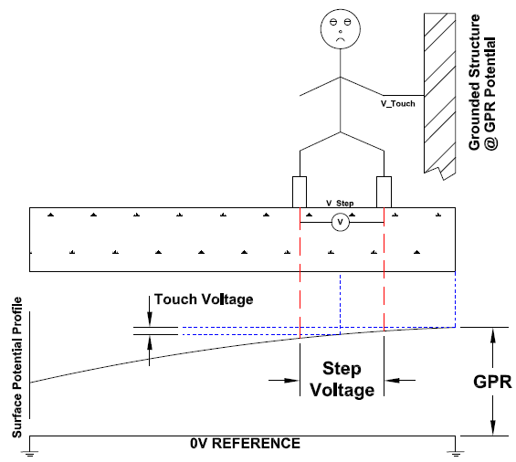
Two terms related to GPR are Step Potential and Touch Potential. Note that both step and touch potentials are direct result of ground potential rise.
Step Potential
Step potential is defined as “The difference in surface potential experienced by a person bridging a distance of 1m with the feet without contacting any grounded object” according to IEEE-Std 80.
Notice the two imaginary points identified in figure 3 above as P1 and P2. Voltage of P1 relative to remote earth is V1 and that of P2 is V2. If the distance between P1 and P2 is 1m and a person put one foot at P1 and another at P2 then he will experience a step voltage of (V2-V1).
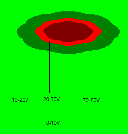
For an example of a ground electrode (earth rod) driven 10ft in to ground with a soil resistivity of 25.25 Ωm, step potential can be plotted as shown in figure 4. Note that as a person steps from one zone to another he will experience a difference of potential and hence shock. Step potential will result in current passing from foot to foot. Center of the figure is the location of earth electrode. It can be seen that step voltage is not a constant and would vary with distance from the center of electrode. Closer the person is to the electrode, steeper or worse the step potential is going to be.

Step potentials need to be controlled in a substation to allow personnel safety. Typically, this is done by performing ground engineering analysis. Common practice is to ‘force’ ground current to flow below the surface either by burying deep ground conductors or having a layer of substation grade high resistivity crushed rock (#57 Granite or equal) on the surface.
Read: Role of Crushed Rock in Substation Grounding
Touch Potential
Touch potential is defined as “The potential difference between ground potential rise [GPR] and the surface potential at the point where a person is standing while at the same time having a hand in contact with a grounded structure.” according to IEEE-Std 80.
When a fault occurs in a substation and ground current flows into the buried ground grid, potential of ground grid in the substation is elevated to value equal to GPR. Since all the metallic objects in the substation are bonded to the same ground grid, all metallic objects (steel beams, transformers enclosures etc) also attain GPR voltage. Now, surface potential (potential where a person is standing) can have another potential depending on the GPR profile (shape of GPR curve from point of fault to remote earth location). Depending on GPR profile there could be difference in potential (voltage) between metallic object that person is touching and surface potential where he is standing. This voltage difference is known as touch potential or touch voltage.
Touch potential will result in current passing from hand to foot. Touch potential need to be minimized in a substation for personnel safety. This is accomplished by making sure surface potentials within substation are kept the same. Adding a layer of crushed high resistivity rock has been shown to minimize touch potentials.
How to reduce magnitude of Ground Potential Rise (GPR)?
GPR can be minimized by controlling following variables:
*Decrease ground grid resistance: Most effective way to decrease ground grid resistance is by increasing the area of the grid, driving deep ground rods, chemical treatment or any other suitable methods.
*Control Path of Fault Current: If substantial amount of fault current can be diverted away from the affected ground rod, then GPR can be controlled. An example of this would be a multi grounded utility distribution system where neutral is grounded at each individual pole. This way the GPR of any single pole is reduced as fault current can have multiple parallel paths.
*Control Magnitude of Fault Current: By controlling the magnitude of fault current the GPR can be kept below the desired limits. An example of this would be to insert resistance or reactance at the neutral-ground connection of distribution transformers. Ground fault current is then limited usually to less than 400A (typically) which will minimize GPR on the distribution sections for a phase to ground fault.
Minimizing equipment damage due to Ground Potential Rise (GPR)
Some ideas to prevent costly communication equipment damage in substation due to GPR are provided below:
*Use optical isolator or copper to fiber converter to break the ground connection from point A to point B.
*Use fiber optic communication channel when communication channel is required from substation to a distant location that could be at different ground potential.
*Investigate if ground loop isolator is practical for your application.
*Design ground grid systems such that all locations of interest are at same potential.
*Within a substation all metallic objects, power and communication grounds need to be bonded to a common ground grid. Grounding (earthing) them separately (as in communication ground, power ground) is not recommended.