Short circuit test is performed on a transformer to measure the equivalent series resistance and reactance. Series resistance provides information about full load copper losses of transformer while series reactance establishes the impedance of transformer. Variable voltage is applied to high voltage winding and low voltage winding is short circuited. Voltage is varied until rated secondary current flows at which time readings are taken.
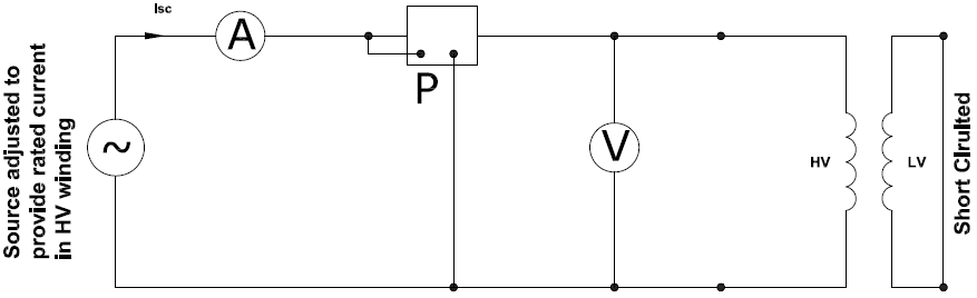
Primary voltage at which rated secondary current flows is noted. This voltage is then divided by the rated primary voltage (times 100) gives the % impedance of the transformer.
Exciting current Iex is very less since the applied voltage will be very low and can be neglected. Hence the entire current Isc recorded on the high voltage winding during short circuit test can be safely assumed to be going through effective series winding resistance and effective series reactance as shown below.
Short circuit and open circuit tests are the two common tests carried out at transformer plant prior to shipping the transformer. Combined these two tests establish the winding loss, transformer impedance, core loss, magnetizing impedance and core loss resistance.
Read: Transformer Open Circuit Test
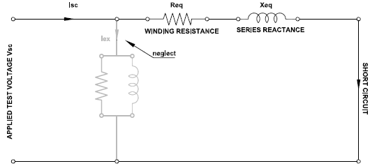
Transformer short circuit test equivalent circuit is shown here. Winding resistance and series reactance are shown as referred to primary circuit. This means secondary winding resistance and reactance are transferred to primary after adjusting for transformer turns ratio.
Transformer short circuit current calculator
Another consideration is that if the HV side is wye connected then the test connections will be across phase-neutral and if delta connected then phase-phase voltage is applied. Measured line current also need to be adjusted for delta HV connection to find out phase current in the winding. This will affect the calculations of winding resistance and leakage impedance. The calculator below accounts for the wye/delta winding and uses appropriate correction factors. The calculator also provides the equivalent core loss resistance in per unit (pu) and calculated transformer impedance [%Z].
Summary
Short circuit test establishes the full load winding power loss (Copper loss) of the transformer. Copper loss is an important parameter for end users as more losses mean energy wasted and also adds additional heating load in the facility. Transformers with less full-load losses are preferred for energy efficiency. Information about the value of copper loss is also useful in certain transient simulation studies as this value determines the resistive damping offered by winding.
Short circuit test also establishes the leakage impedance (% Z) of transformer which is used in short circuit simulation studies and other power engineering studies. Leakage reactance also contribute to reactive power requirement of power transformer.