High magnitude current lasting few power cycles during switching on a power transformer is known as transformer inrush current. Magnitude of inrush is dependent on when the switch is closed in voltage cycle, core residual flux, system source impedance, transformer size, type and system grounding. Inrush current can result in nuisance tripping of protective devices such as fuses, circuit breakers and also create large mechanical force within the core and coil of transformer. Inrush current is a byproduct of transformer physics and there are not many ways that an engineer can control inrush current.
In early history of transformer, inrush current was not frequently experienced as core was operated at lower flux density due to high core losses. Due to improvement in loss properties of core steel it has now become possible to operate core at higher flux density. Higher inrush in modern transformer is a byproduct of operating transformer at higher core flux density as transformer efficiency is improved. In United States for example the DOE (Department of Energy) standard released in 2016 require further increase in efficiency of transformers. Improved efficiency standards usually but not always result in higher energization inrush currents.
Read: Transformer Excitation Current
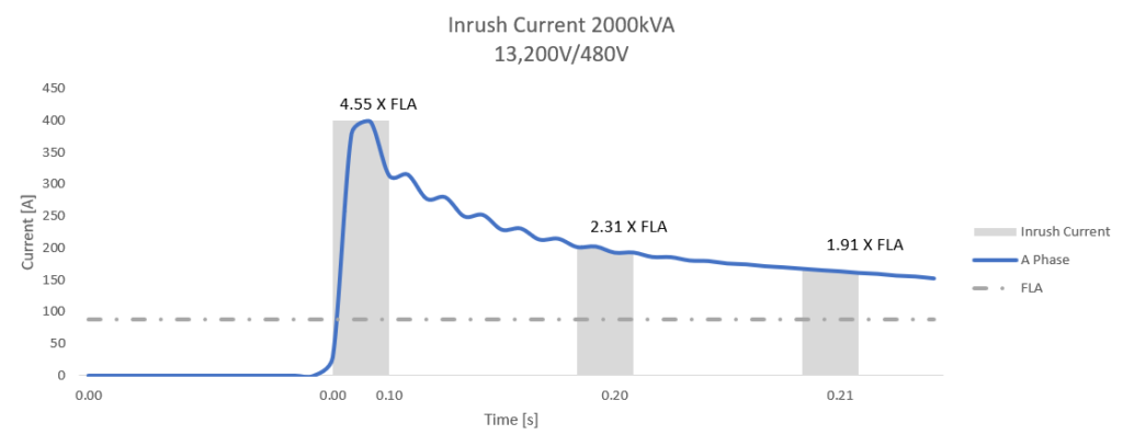
Actual RMS current during energization of a 2,000kVA transformer from a utility source is shown below. Note that the maximum inrush is 4.55 times full load current [FLA] at 0.1s, 2.31xFLA at 0.2s and 1.91xFLA at 0.21s for this specific example.
Parameters that determine inrush current
When transformer is energized, current many times nominal full load amperes [FLA] will flow for few cycles. Current could be anywhere from 3-14 times FLA of transformer and typically last up to 0.1s and in some special cases up to 1s. Some factors that determine magnitude and duration of inrush current are:
- Point of voltage waveform switching
- Magnitude and polarity of residual magnetism in core
- System damping
- Winding energized- primary or secondary
- Transformer size
- Transformer construction
- System grounding
1.Point of voltage waveform switching
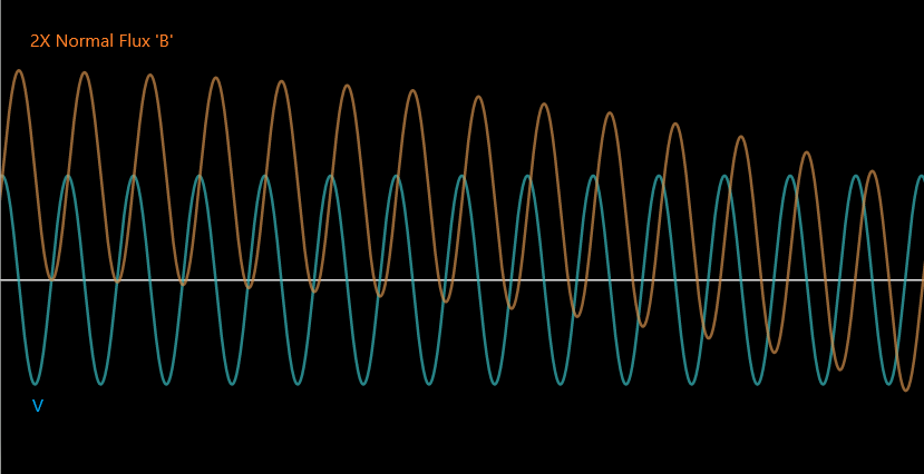
Under nominal conditions, magnetic flux in transformer core will be 90 degree out of phase with voltage. This means when voltage wave passes through zero, flux will be at its peak. When transformer is energized at zero voltage crossing, to maintain the first half cycle voltage wave the flux has to reach twice the normal flux density. While the flux density can only reach twice the normal value, the current drawn from primary circuit will be many times nominal. This is because of the shape of BH curve.
Read: Comparison of Core and Shell Type Transformer
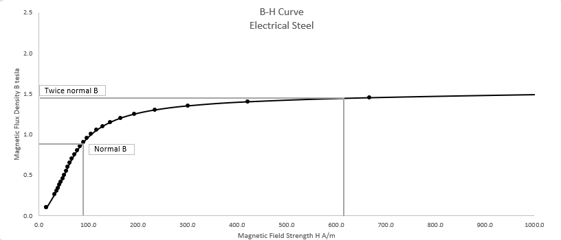
From B-H curve it can be seen that twice the magnetic flux density [B] will drive the core steel deep in to saturation. For twice the normal flux density the current drawn (which is proportional to magnetic field strength H) can be very high. Current drawn could be any where between 3-14 times the nominal full load current (FLA) of transformer. Current will also have a peculiar ‘peaky’ wave shape with prominent second and third order harmonics.
In practice, flux B does not quite reach the maximum theoretical limit of 2 times nominal. The source impedance of primary circuit will limit the current and hence maximum flux density reached will be smaller than 2 times nominal flux density.
Read: Transformer Open Circuit Test
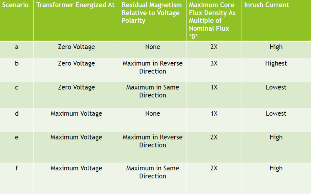
There are six conditions to consider for point of wave transformer switching:
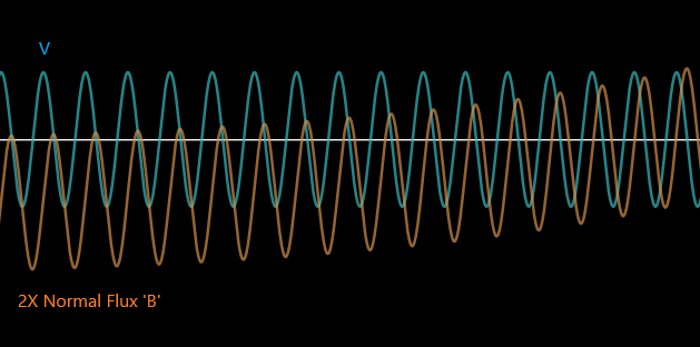
a. Switching at zero voltage crossing-no residual magnetism
In this scenario transformer is switched on when voltage waveform is passing through zero. There is also no residual magnetism in the core.
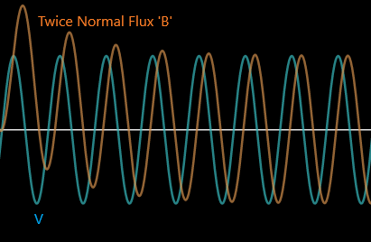
Graph of switching a transformer under this scenario is shown in figure 4. Remember that flux ‘B’ in the core is always 900 out of phase with system voltage. Since flux is starting from zero at the instant of switching, it must ‘catch up’ with the voltage wave. The only way it can do is to have the first half cycle flux twice the nominal flux ‘B’.
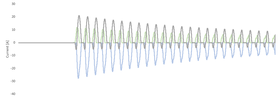
Twice maximum flux density is the theoretical maximum flux density that core can attain in this scenario. However, inrush current drawn under this scenario can be many times nominal full load current. This is due to the shape of the B-H curve shown in figure 2. The flux waveform saturates the core in ‘one direction’ and transformer will draw pulses of inrush current every other half cycle with a heavy DC component. This can be seen in figure 3. Remember that flux controls the effective impedance. So, when core saturates, effective magnetizing branch impedance drops from (very high value ~100s of Kohm) to air-core impedance of the winding which is roughly same magnitude as transformer’s leakage impedance.
Practically, transient flux does not reach twice normal flux density due to large current inrush through the primary circuit and resulting voltage drop. But as can be seen from B-H curve of figure 2 even for a flux lower than twice maximum significant inrush current can flow.
b. Switching at zero voltage crossing-maximum residual magnetism in reverse polarity
This scenario will have transformer switched on during zero voltage crossing with a residual magnetism in the opposite polarity to that which varying flux would normally have. This case makes the scenario considered in ‘a’ much worse.
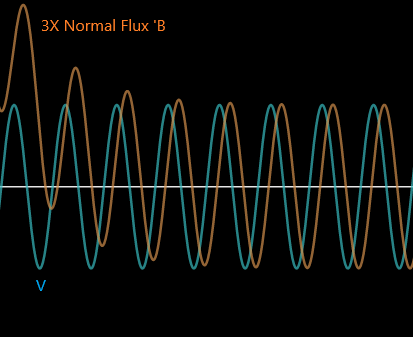
At zero crossing of voltage waveform, transformer is energized with residual flux ‘B’ in the opposite polarity. This means first cycle flux would have to reach a value higher than in case ‘a’ by a value equal to B. Remember in case ‘a’ flux had a theoretical value of ‘2B’. So, in this scenario theoretical maximum flux attained will be 2B+B=3B i.e. three times nominal flux density which results in even higher current inrush than case ‘a’. Inrush current will also take longer time to reach steady state conditions.
Practically, transient flux does not reach three times the normal flux density due to large current inrush through the primary circuit and resulting voltage drop.
c. Switching at zero voltage crossing-maximum residual magnetism in same polarity
This scenario will have transformer switched on during zero voltage crossing with a residual magnetism in the same polarity to that which the varying flux would normally have. This case is an ideal situation and there will not be any inrush current theoretically.
Practically, having a residual magnetism of same polarity and magnitude as the varying flux would normally have is rare. Even if the residual magnetism has the same polarity, its magnitude could be lower than ‘B’ which would result in some inrush current.
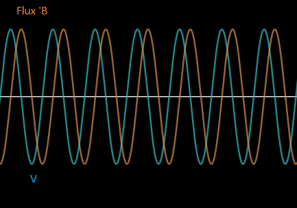
d. Switching at maximum voltage crossing- no residual magnetism
This scenario will have transformer switched on during maximum voltage with no residual magnetism.
This case is an ideal situation as there will not be any inrush current theoretically. Remember that flux ‘B’ in the core is always 900 out of phase with system voltage. Since the switching occurs at peak voltage, flux can easily start from zero and attain its nominal value. There will not be any inrush current in this scenario.
e. Switching at maximum voltage crossing- maximum residual magnetism in opposite polarity
This scenario will have transformer switched on at peak voltage with a residual magnetism in the opposite polarity to that which the varying flux would normally have.
Maximum flux density will have a value equal to twice the normal flux density with a corresponding high inrush current similar to case ‘a’.
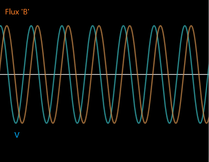
f. Switching at maximum voltage crossing- maximum residual magnetism in same polarity
This scenario will have transformer switched on at peak voltage with a residual magnetism in the same polarity to that which the varying flux would normally have.
Maximum flux density will have a value equal to twice the normal flux density with a corresponding high inrush current similar to case ‘a’.
Summary of all possible scenarios for point of wave transformer switching inrush is given below:
2. Magnitude and polarity of residual magnetism in core
Residual flux magnitude will depend on quality of steel and point of wave at which transformer is deenergized. Remember that flux lags voltage by 90 degree. This means that when transformer is de-energized at peak voltage, residual flux will be zero and when de-energized at zero voltage, residual flux will be at its maximum. Type and quality of core steel determines how much residual flux (remnant flux) is stored. In general, higher the quality of steel, larger the remnant flux and greater the inrush current.
3.System Damping
Source impedance has some influence in the magnitude and duration of transformer inrush. The relationship between peak inrush current and source impedance is given by [1]:
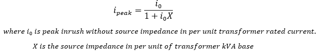
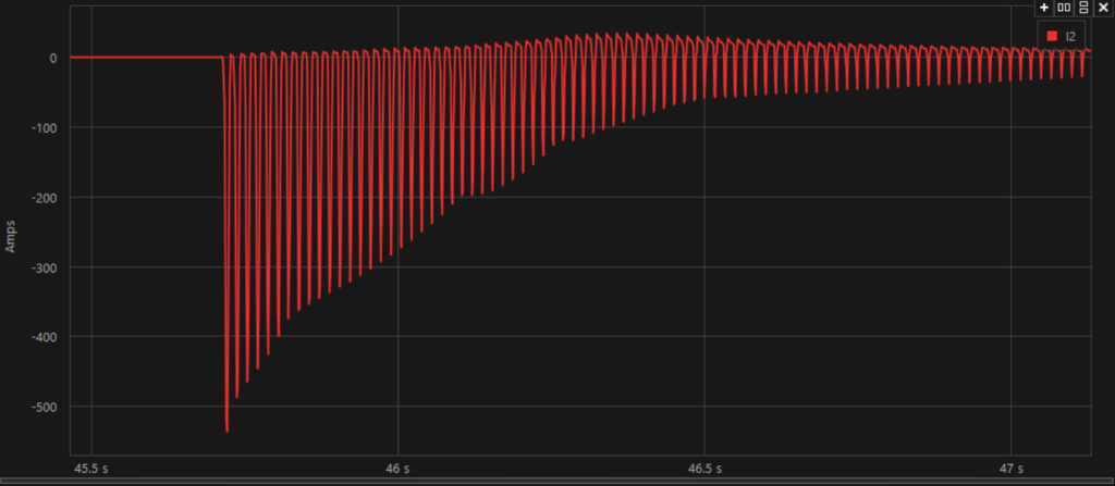
X/R ratio of the transformer energization circuit influences the duration of the transient. Higher X/R ratio will create larger DC offset in the inrush current. Large DC offset creates large DC flux in transformer core. DC flux decays slowly prolonging the inrush.
Figure below shows a 2.5MVA 13,200V generator energize a chain of distribution transformers and the circuit has high X/R ratio of ~15. Note that the inrush persists for a long duration. For this specific example inrush has not completely died down even after 1.4s!
Winding resistance provide additional damping to transient switching oscillations. Transformers with low winding resistances (example would be low temperature rise transformers) tend to have inrush current persist for longer duration. This means 80deg C transformer could have a higher inrush current at 0.1s compared to say 150deg C transformer.
4.Winding Energized-Primary or Secondary
Among other things inrush current depends on the length and diameter of coils and the number turns in the energized winding. Smaller the diameter (or length of turn), higher the inrush. For step down applications, secondary low voltage winding is wound close to core and primary HV winding is on top of secondary winding. So, if this stepdown transformer is back fed and used as a step-up unit then higher inrush up to 2-3 times the normal inrush current can be expected.
5.Transformer Size
Larger the kVA larger the inrush current. However, on a per unit basis relative to their rated full load current, smaller transformers draw much more inrush current especially 500kVA and below. Inrush in smaller transformers also die down more quickly than larger transformers.
Three phase transformers typically have inrush current less than the corresponding single-phase models.
Read: Transformer Short Circuit Test
6. Transformer Construction
Transformer inrush current can be calculated by following formula:
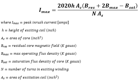
Higher Inrush will result for:
- Larger transformers (large h, large core area Ac)
- Transformer with residual (remnant) flux
- Operating transformer core at higher flux density
- Transformer operating with high Volt/turn (low N)
- Transformer with small primary winding area (larger As)
Lower Inrush accomplished when:
- Small transformers (small h, small core area Ac)
- Transformer with no residual (remnant) flux
- Operating transformer core at low flux density
- Transformer operating with lower Volt/turn (high N)
- Transformer with larger primary winding area (larger As)
Transformer with high BIL also tend to have larger inrush. This is due to transformers possibly having larger size and clearances and possibly due to operating at a higher volts/turn due to coil spacing.
One reason primary winding is wound on top of secondary (among other things) is to achieve larger winding diameter and thus lower inrush current. Winding that is closest to the core will experience large inrush (smaller winding diameter) compared to winding outside. This is the reason for very high inrush current when transformer designed for step down application is used for stepping up.
Liquid filled transformers have lower inrush compared to similar size dry type units. This is because liquid filled transformers are smaller (less height, smaller core area) and they also operate at a much lower volts/turn.
7. System Grounding
Wye-Wye (star-star) connected transformers with primary neutral connected to ground and applied in grounded source will have around 50% higher inrush current compared to transformers applied on ungrounded source.
Transformer Current Calculator
References:
[1] Electric Power Distribution Handbook [T.A Short]