In this article an actual fault waveform captured on high impedance bus differential relay at 13.2 kV is discussed. Fault inside the switchgear was cleared by bus differential relay in 3.94 cycles and prevented costly damage to the gear. After cleaning and testing, gear was able to be quickly put back in service. Fault was initiated by rodent entering the switchgear which created phase-phase short circuit.
Read: High Impedance Bus Differential Protection
This example illustrates the known fact that bus differential relaying is extremely fast in clearing internal bus faults. For this example, fault is cleared in 3.94 cycles (65ms @ 60Hz) which includes lockout and breaker operate time. Overcurrent relays cannot be set sensitive enough to clear bus fault and will typically take much longer to clear. This is because overcurrent relays NEED to coordinate with other relays whereas bus differential NEED NOT coordinate with any other relays. Due to very fast clearing time, bus differential relays are also beneficial in reducing arc flash energy.
Read: Phase -Phase Short Circuit Waveform
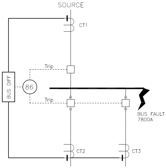
Circuit below shows the wiring schematic for high impedance bus differential relay (87Z) for this specific example. 87Z is configured to trip lockout relay (86) which in turn trips main and feeder breakers. Once 86 trips, CT secondary current is shunted away from 87Z relay. This is done to minimize duration of voltage rise across the relay impedance. MOV connected across the impedance limits the voltage to a safe value.
![Basic relay scheme [A Phase Shown]](https://voltage-disturbance.com/wp-content/uploads/2021/01/Basic-relay-scheme-A-Phase-Shown.png)
Waveform below shows the typical sequence of operation and waveform we can expect to see in an actual bus fault cleared by high impedance differential relay. Top graph shows the current as measured by over current relay ’50 element’ which is connected in series with 87Z. Bottom graph shows voltage developed across the high impedance inside the 87Z relay. Note that this voltage is clamped at 1,500V for this specific relay. Relay was set to initiate trip when voltage across relay impedance is greater than 200V.
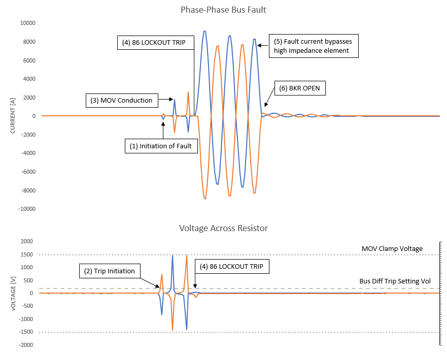
In figure 3, there are four areas of interest, (1) is where phase-phase bus fault initiates. At (2) voltage across 87Z crosses bus differential trip setting (200V) and relay initiates trip to 86 lockout relay. Lockout relay (86) takes around 1.25 cycles to open at (4). At this stage remember that only 86 lockout has opened and breaker still hasn’t opened. Bus fault hence is not yet extinguished. CT secondary current now flows bypassing the high impedance 87Z relay and its magnitude is significantly higher (5) due to this fact. At (6) after additional 3 cycles, breaker opens and clears the fault. Note from bottom graph that MOV inside 87Z relay clamps the voltage to 1,500V and in the process conducts current which can be seen in (3).
Read: Phase to Ground Fault Waveform
After 86 lockout trips (4), current through the 50 element (Instantaneous over current) increases (study figure 2 to understand why). This element can be used for backup trip in case 86 fails to clear fault. This over current trip can be sent to upstream breaker after applying some time delay. Overcurrent element (50) is usually available in most modern high impedance differential relays. It is usually an option to wire the 50 elements in series with 87 but not a requirement. It is preferred that these be wired in series for added protection.
Conclusions
*High impedance bus differential relay (87Z) detects internal bus fault EXTEREMLY fast. For this specific example 87Z asserted trip signal approximately ~1-2ms after initiation of fault.
*MOV inside 87Z clamps the voltage to 1,500V. This is the voltage that CT secondary leads will experience. Other relay vendors may have MOV clamp voltage at 2,000V or other.
*Once relay issues trip to lockout relays it takes ~1.25 cycles to open its contact. This also bypasses current from 87Z and prevents MOV inside 87Z from conducting longer (and hence deteriorating).
*It may be beneficial to have the 87Z relay trip the lockout and also main and feeder breakers at the same time. This will reduce fault clearing time by ~1.25 cycles for the example shown. Drawback is that relay needs as much output contacts as there are breakers to trip.
*Overcurrent element (ANSI 50) can be used as a backup protection in case lockout fails to open all the breakers.
Read: CT Saturation, How to select taps on multi ratio CT, Open circuit CT