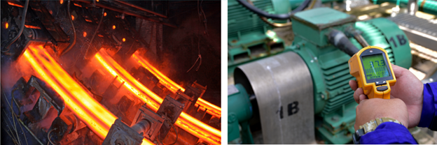
Temperature kills motors. Temperature is the most common cause behind motor damage. A 10-degree centigrade increase in insulation temperature decrease the insulation life by half. An ideal motor insulation should have the highest temperature rating while operating at the lowest operating temperature giving motor some margin for occasional overload and voltage unbalances. This article discusses typical NEMA motor insulation ratings, winding temperature protection, preventing nuisance RTD trips and common causes behind motor over temperature.
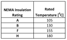
NEMA designations for motor insulation temperature ratings are designed by letters A, B, F, and H.
With advancements in motor construction materials and design, it is possible to construct motor with class F insulation (1550C) while only operating with a temperature rise corresponding to a class B motor (1050C). This provides a large margin of 500C which will significantly increase the life of motor. These motors are designated as F/B motors.
A term that is frequently used with insulation temperature rating is allowable ‘temperature rise’. What is temperature rise? Temperature rise in a motor is the allowable increase in motor winding temperature above an assumed maximum ambient of 400C. This rise in motor winding temperature is caused due to core losses, winding losses within the motor as it is energized and operating with or without load.
Motor starting current calculator
NEMA specifies allowable temperature rise for motors operating under full load and at rated service factor.
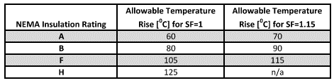
Allowable temperature rise is based on a 400C ambient meaning a class B motor with a rise of 800C when operated at 400C ambient will have an insulation temperature of 80+40=1200C. Ten-degree difference from maximum allowable insulation temperature is to allow for ‘hotspot’ temperature in the interior of the winding. Note however that when embedded temperature sensors (RTD, Thermocouple etc.) are used, the allowable rise is 100C higher than that shown in table 2. This is because unlike resistance-based method of temperature measurement, having embedded sensors will help measure temperature much more accurately hopefully capturing the ‘hotspots’ inside the motor. Resistance based method is discussed further down in this article.
Read: Single phase motor starting
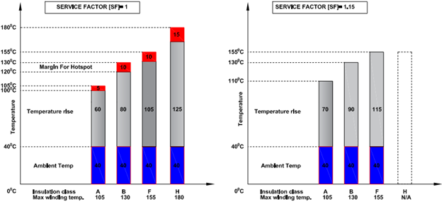
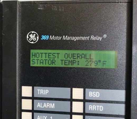
Figure 1 shows graphically the temperature rise for motor with SF of 1 and 1.15. Service Factor [SF] is a multiplier that is applied to rated power. A 1.15 SF motor can be operated 15% above its name plate rating. However, operating continuously at SF above 1.0 can reduce the life in addition to affecting performance such as full load RPM, full load current. Note from figure 1 that there is no allowance for hotspots when operating at 1.15 SF. When operating at 1.15 SF, the hot spot temperature can exceed the insulation rating resulting in reduced motor life.
Read: Incorrect motor control circuit wiring
Resistance method of determining motor temperature rise
For motors without embedded sensors (RTD, PTC etc.), temperature of the stator winding can be calculated based on resistance of the winding. Resistance of winding is measured at ambient condition and after operating under load until temperature stabilizes (possibly up to 8 hours). A milli-ohm meter needs to be used for measuring winding resistance.
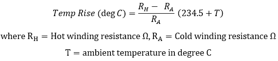
If ambient temperature changes during test, then the delta temperature change need to be added or subtracted from the calculated value. Many medium to large HP motors are equipped with embedded sensors such as RTD.
Recommended temperature protection settings
RTD alarm temperature should be set at or below the maximum temperature rating for the insulation. Adjust as needed for the service factor (SF) or nonstandard ambient conditions, altitude etc. Suggested initial RTD temperature settings are given below. Revise the settings after temperature is trended for a year under various ambient and load conditions. For special construction motors or large MV motors consult manufacturer.
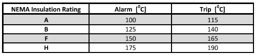
Motors with F/B motors may be set to ‘B’ rise temperature trip instead of temperature rise allowed by ‘F’ insulation.
Prevent RTD nuisance trips
Ensure the relay has logic in place to detect open and short RTD. An open RTD could mean ‘infinite’ temperature and should not lead to trip condition. Instead, an open or short circuited RTD should trigger an RTD alarm on the relay.
Enable ‘trip voting’ wherein at least two RTD need to have temperature above the trip setting for the relay to initiate a trip. Trip voting is only used for stator RTD and has been shown to be very effective in preventing nuisance trips due to single RTD failure or loose connection.
Link to: Motor current calculator
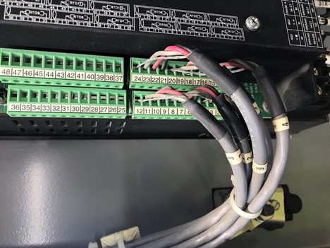
Ensure RTD extension cable shield is only grounded at one location (usually the shield terminal is internally connected to earth ground inside the relay). If shield is intentionally or unintentionally grounded at two or more locations, circulating shield current can cause a proportional current to flow in RTD sensing circuit causing nuisance trip.
Ensure shielded twisted cables are used for RTD extension cables.
Ensure RTD cables, connections are tight and there is no corrosion. Loose connection or corrosion can cause resistance in the sensing circuit to increase causing nuisance trips.
For additional discussion on RTD and RTD extension cable refer to: Over temperature protection using RTD.
Possible Causes of Motor Over Temperature
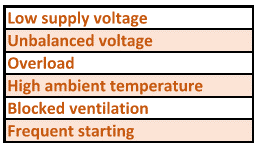
If motor has tripped on overtemperature and is not a nuisance trip, then investigation need to be carried out to find out the cause behind over temperature. Common causes behind motor over temperature are listed in table 4.
Low supply voltage can cause constant impedance load like motor to draw more current to support the give shaft load. Low supply could be due to bad utility supply or issues with transformer tap changer or poor power factor.
Unbalanced supply voltage can cause unbalanced current to flow in the winding. Unbalanced voltage will have negative sequence components which cause negative sequence current to flow in the windings. Induction motors offer lower impedance to negative sequence current and can quickly overheat. This topic is further discussed in this article.
Overload: This is one of the common reasons for motor over heating and needs to be quickly taken care of to prevent motor damage.
High Ambient Temperature: High ambient temperature can cause motor insulation temperature to rise above the insulation rating of winding. High ambient is usually caused by having motor in a room that is closed to outside air such as basements, cellars etc.
Blocked Ventilation: Another common reason for motor overheating is blocked ventilation. Often dirt and debris will collect on the ventilation holes and impede flow of air through the cowling.
Frequent Starting: Every time a motor is started, a large amount of current (locked rotor current) is drawn causing rapid heating of windings. Under normal conditions this rapid rise will be followed by thermal equilibrium as the motor picks up speed and fans start cooling the winding. However, if the motor is started frequently then the winding temperature will keep increasing with not enough time to cool. If frequent starting cannot be avoided, then one of the reduced voltage starting method may be employed. Some examples are star-delta starting, auto transformer starting, Variable speed drive starting, soft start etc.