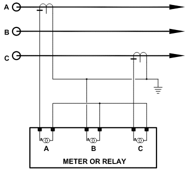
It is possible to do three phase current measurement using just two current transformers (CT) in electrical systems with neutrals that are ungrounded or otherwise high resistance grounded. This is possible due to the magic of vector addition. Figure 1 shows the wiring schematic where phases A and C are metered using CT while phase B current is a calculated vector. Vector summation is accomplished by the way phase A and C leads are interconnected and fed to B phase current channel. The current thus calculated will be the actual B phase current except when measuring very low current and the system has a ground fault condition.
Read: CT Shorting Blocks

This scheme can also work in situations where the neutral is solidly grounded and there are no phase-neutral connected loads (e.g., an MCC with only 3 wire loads) and measuring ground fault current is not a requirement. For measuring ground fault current a three phase CT will be required.
The method of using two current transformers to measure three phase current is attractive for simple metering applications, locations where mounting three CT is a space constraint and for saving on material and installation costs.
Few things to consider while applying two CTs to measure three phase current:
- CT polarity is very important.
- Only make one ground connection as shown in figure 1. Making two ground connections create parallel path for current and will lead to erroneous reading.
Read: How to select taps for multi ratio CT?
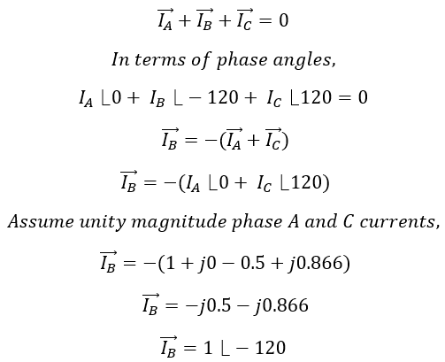
Mathematical Proof
Per circuit theory, a set of three phase current vectors under ideal conditions should vectorially add to zero.
Read: Open circuit CT characteristics
The derivation above shows that by only using A and C phase currents, B phase current can be ‘calculated’. Similarly, any phase can be calculated by measuring the other two phases. Since the calculation is vectorial, direction of current and hence the polarity of CT mounting is critical.
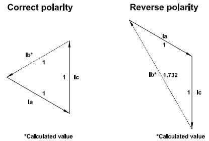
Figure 2 show the vectors when CTs are wired with correct polarity and when one CT is wired in reverse polarity. If the calculated phase (B phase in this example) is reading 1.732 times the expected value, then it’s a sign of reverse CT polarity.