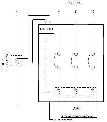
Neutral Current Transformer [NCT] is required for residual ground fault detection and power metering in three-phase four wires systems. Residual connected scheme is the common ground fault protection method in low voltage (<1000V) switchgear and switchboard applications. This method relies on phase cancellation, meaning current in all three phases plus the neutral current should add to zero under normal condition.

During ground fault the above equation will not add up to zero and will show a real number. This value is the ground fault current.

Modern electronic trip circuit breakers have built in inductive current sensors [Rogowski or similar] which produces a voltage signal in proportion to current. For residual measurement it is not sufficient nor feasible to connect a traditional iron core current transformer [CT] on the neutral bus. Electronic trip units can only support current transformers [current sensor would be a more appropriate name] that produce proportional low voltage signal similar to Rogowski coil. This is where NCT need to be compatible to work with electronic trip units. Usually these are vendor specific, and each trip unit will have a defined set of NCT that would work with it.
Read: Zero Sequence Current Transformer
Neutral Current Transformers that are used with electronic trip circuit breakers should be called Neutral Current Sensors though in general industry do not follow this practice. For the purpose of this article neutral current CT and neutral current sensor are assumed to be the one and the same and uses Rogowski method for current sensing. Neutral CT that is iron core is not part of this discussion.
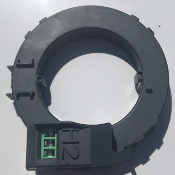
Figure 3 shows a 1200A neutral current sensor. This is a current sensor that is meant to work with a specific manufacturer electronic trip unit.
![Cutaway section of Neutral sensor [Left], Core exposed [Right]](https://voltage-disturbance.com/wp-content/uploads/2022/07/Cutaway-section-of-Neutral-sensor-Left-Core-exposed-Right.png)
Inside of this sensor we can see typical Rogowski coil arrangement. The coil produces a voltage (few mV to few volt) proportional to the current flowing through its window. Figure also shows neutral current sensor with some coil removed. We can see the clear plastic core material which is hollow inside indicating that these sensors are air cored. These sensors are not subject to saturation and can be open circuited without any issues. Detailed discussed on Rogowski coil technology is found in this article.
Read: Open circuit Current Transformer
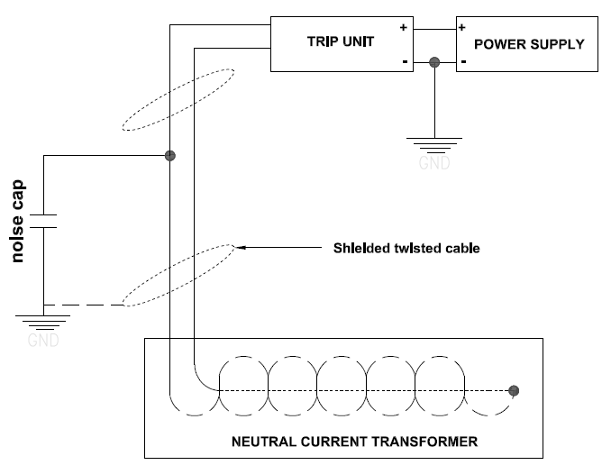
Typical connection of neutral sensor to electronic trip unit is shown in figure 4. Each vendor will have a slightly different variation of this. Sensor coil is fed to the trip unit and is usually connected to a noise capacitor to filter out high frequency noise from entering the trip unit. A shielded twisted cable is also recommended between the NCT and the trip unit as the signal in this section of wire is very low voltage (mV to few volts range).