Current Transformer [CT] shorting blocks are used to bypass CT secondary current flowing to the connected device by inserting a ‘short circuit screw’. After inserting the shorting screw, the connected device (meters, relays etc.) can be safely removed at which time the current will circulate between the CT and the shorting terminal block thereby preventing open circuit CT. CT shorting blocks are useful during periods of maintenance or upgrade of devices connected to CT.
An iron core CT should never be open circuited as it can produce dangerous voltage as described in this article. High voltage produced due to open circuited CT can be a shock hazard as voltage over 6kV can be produced when some large ratio CT secondary is open. High voltage may eventually damage the secondary lead insulation and is also a fire hazard. Due to these reasons a CT shorting block is recommended when iron core CTs are used. For CTs with high risk of open circuit, an open circuit protector is recommended.
Open circuited current transformer characteristics
Shorting block is not required when current sensors or Rogowski coil based current transformers are used. The reason for this is that current sensors or Rogowski coil produce a low secondary voltage in proportion to primary current. Air core CT also don’t need shorting block as these CT do not have enough ‘strength’ to produce voltage when secondary is open circuited. In summary CT shorting blocks are only required for iron core current transformers.
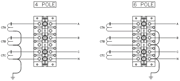
Typical CT shorting block wiring diagram
A typical wiring diagram of a 4 pole and 6 pole shorting block is shown in the figure below.
4 Pole vs 6 pole CT shorting block comparison
Three phase CT will have a total of six secondary leads. Six pole shorting block will allow all six wires to be wired and terminated. The common return circuit is ‘created’ at the shorting block. See figure 1.
Read: How to parallel current transformers?
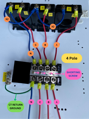
Alternate is to use four pole shorting block where the common return path is made local to the CT and only four wires (three phase wires + return) is brought to the shorting block. See figure 1.
Read: Series connection of current transformers
Features of four pole shorting block:
- Common return is made at the CT itself.
- CT leads can be conveniently grounded at the CT return common point or at the shorting block.
- Only 4 leads from CT are brought out and terminated on four pole block and then 4 wires continue to meter or relay.
- Effective CT lead circuit length when four pole shorting block is used is 33% shorter when compared to using six pole shorting block for symmetrical three phase current flowing through CT. Four pole shorting block has an advantage here. See figure 4.
- Effective CT lead circuit length when four pole shorting block is used is same when compared to using six pole shorting block for non-symmetrical single-phase current flowing through CT. Four pole and six pole shorting block have same circuit length. See figure 4.
- Only one lead from each CT is accessible and hence it is harder to troubleshoot.
Features of six pole shorting block
- Common return is made at the shorting block.
- CT leads can be conveniently grounded at the shorting block.
- All 6 leads from CT are terminated on this block first and then 4 wires continue to meter or relay.
- Effective CT lead circuit length when six pole shorting block is used is 50% longer when compared to using four pole shorting block for balanced three phase current flowing through CT. See figure 4.
- Effective CT lead circuit length when six pole shorting block is used is similar when compared to using four pole shorting block for non-symmetrical single-phase current flowing through CT. See figure 4.
- Each CT leads can be individually accessed and hence it is easy to troubleshoot.
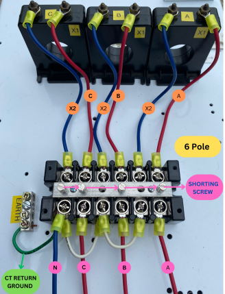
Figure 4 is used to gather the circuit length information for comparing four pole vs six pole CT shorting block. Assume each section is of unit length and ignore the length of jumper connections. At the neutral point of the meter where all three CT phase wires are connected, under balanced current condition, current would add to zero. For this reason, remaining circuit length can be ignored as the wires are not carrying any current.
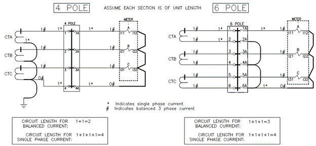
From the figure 4, for balanced current condition, four-pole block has a circuit length of ‘2’ whereas six pole block has a length of ‘3’. Hence, we can state that four pole CT terminal block has 33% less circuit length when compared to six pole block for the scheme shown. Stated in other words six pole CT terminal block has 50% more circuit length when compared to four pole terminals for the scheme shown.
For unbalanced single phase current condition, the circuit length for four pole and six pole terminals are similar.
SHORTING BLOCK FOR MULTI RATIO CT
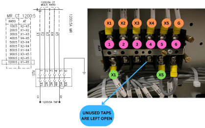
Multi ratio [MR] CT allow user to select the ratio needed from a specific set of available ratios. The ratios are published on the CT name plate. Read this article to obtain additional information on selecting taps for multi ratio CT.
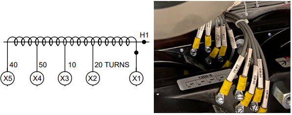
It is recommended to wire all the taps to the CT shorting block rather than wiring only the taps needed for the specific application. By wiring all the taps to a CT shorting block, changes to CT ratio can be made easily at the shoring block instead of having to perform wiring changes inside the electrical equipment. Unused CT taps need to be left open. A set of three phase CT will need three separate shorting blocks when MR CTs are used.
What are the recommended locations for CT shorting block?
Since the purpose of a CT shorting block [CTSTB] is to provide easy maintenance access for relays and meters, the mounting location need to be accessible. Typically, shorting blocks are installed in instrument compartment or in locations close to the connected device.
What is the best location to ground a CT?
CT is usually grounded at the shorting terminal block for easier visual confirmation of grounding. CT can also be grounded at the common return point of the CT though this is not common. Grounding a CT at more than one location on the circuit has to be avoided as this can lead to fault current flowing through CT leads in the event of an external fault.
Read: CT failure due to capacitor bank discharge current
Precautions while shorting a CT
To avoid any nuisance trip while CT is being short circuited, make sure the protective relay connected to the CT do not have current unbalance protection or negative sequence protection. The act of shorting the terminals can create a current unbalance condition that can activate protection system if enabled.
At the conclusion of any repair, ensure CT leads are circulating ratio current to confirm CT circuit is not left open circuit by mistake.