Stray voltage is defined by IEEE as “A voltage resulting from the normal delivery and/or use of electricity (usually smaller than 10 volts) that may be present between two conductive surfaces that can be simultaneously contacted by members of the general public and/or their animals. Stray voltage is caused by primary and/or secondary return current, and power system induced currents, as these currents flow through the impedance of the intended return pathway, its parallel conductive pathways, and conductive loops in close proximity to the power system. Stray voltage is not related to power system faults and is generally not considered hazardous”.
Stray voltage typically means the voltage between neutral and earth. Stray voltage is the voltage across two surfaces that can be simultaneously contacted by person or animal. Voltage between a substation and a grounded structure location 100ft away is not stray voltage according to the definition above as no person or animal can simultaneously contact these two locations 100ft apart. Factors affecting stray voltage are:
- Long single-phase distribution lines or three phase four wire systems with unbalanced load.
- Multipoint grounded utility distribution circuits.
- Neutral return conductor that is undersized or otherwise has high impedance.
Note: In this article, terms ground and earth are used interchangeably and means same physical earth.
Another term that is important to understand while discussing stray voltage is Contact Voltage. Contact voltage is the voltage resulting from abnormal system conditions such as: short circuit, open circuit, wiring errors etc. In other words, stray voltage is experienced continuous and contact voltage appears only during a system fault.
Read: Ghost or Phantom Voltage
There are two mains methods by which stray voltage is created:
- Neutral current and voltage drop across neutral circuit impedance
- Neutral to earth current and voltage drop across earth impedance
Stray voltage due to- Neutral Current
Consider a single-phase line with phase and neutral conductors. Current flowing through neutral conductor impedance creates a neutral conductor voltage drop when measured with respect to ground. Even for a three-phase circuit, unbalance current returning through neutral can create voltage drop. Voltage measured between Neutral, and Earth is known as Neutral-to-Earth Voltage [NEV].
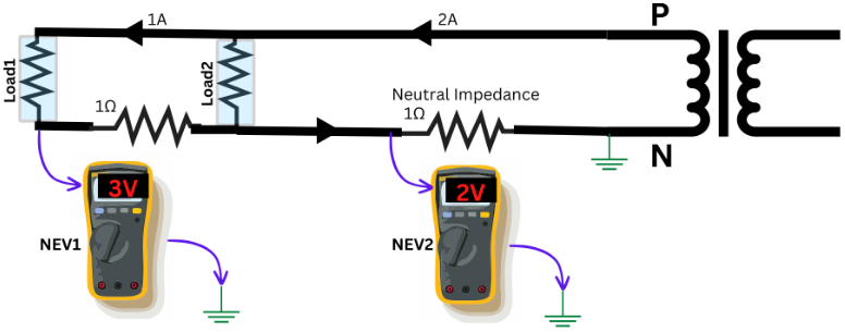
Figure 3 shows an example of NEV measured at a rural 220V distribution system similar to figure 2. For this installation, neutral is only bonded to earth at the remote utility substation transformer which is the prevalent practice in most countries except in North America. Since rural circuits can be long, the sum of neutral currents from all the circuits creates large neutral voltage drop.
Read: Single point grounding in power systems
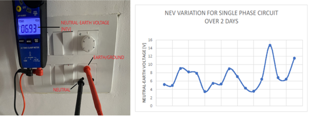
In this specific example [Figure 3], NEV do not create a stray voltage condition since neutral is not connected to ground in this application. However, this perfectly illustrates the concept of NEV. If neutral was tied to ground at this location, all exposed metal parts in that house will get ‘energized’ at 6.93V (Voltage shown on multimeter in figure 3). In North American installations where neutral is tied to ground at each individual house panel, neutral potential gets transferred to ground circuit. In this authors opinion, there are few reasons NEV does not get as high as in figure 3 (typically) for North American installations:
- Single phase distribution circuits even in rural area is at medium voltage level. Higher the voltage, lower the current and hence lower the neutral voltage drop.
- LV circuit distribution circuits are typically very short meaning a single transformer at the most will feed two to four houses. Contrast this with Asian distribution where the secondary (440V/220V) circuit could be many miles long and serves hundreds of customers.
If the neutral was tied to earth for this example, readers can appreciate the fact that NEV potential will get ‘transferred’ to earth. This is one mechanism of stray voltage generation.
Read: Power quality checks with multimeter
Stray voltage due to- Neutral to Earth Current
In some parts of world (and definitely in North America), utility neutral is connected to ground at every pole or every 0.25mile. This is known as multi-grounded system and is done for reasons of safety, protection, coordination, voltage stability, lightning protection etc. While this grounding method has some advantages, it also causes neutral return current to enter the earth uncontrollably. According to Electric power Research Institute [EPRI], up to 60% of neutral current in a multi-grounded system returns to source substation over earth. Practice of allowing current to flow uncontrollably over earth is a uniquely North American practice and may have been an unintended consequence of following multi-grounding due to its advantages listed above.

Another practice that has led to uncontrolled release of neutral return current to earth is the use of bare concentric neutral cable for URD [Underground Residential Distribution]. These cables came to market in 1950’s and 60’s and cost less since they lack outer jacket. Bare outer neutral was sized for one-third of phase ampacity and the assumption was that remaining current will return over earth. While the use of bare concentric neutral wires may have decreased, there are many thousand miles still in service.
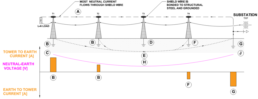
Consider a long (5+ mile) radial single phase distribution line as shown in figure 5. Current flows through phase conductor and returns through shield wire which is also the neutral conductor. For this multi-grounded system, neutral is also connected to earth/ground at each pole. Refer to the notes listed on the drawing in figure 5, explanations are given below.
A: Neutral return current flows through shield wire which is the designated return current path.
B: Some neutral current returns through physical earth for poles that are far away from source substation.
C: Flow of neutral current through earth resistance of each pole will result in neutral-earth voltage [NEV]. NEV will be high at tail end locations for long distribution lines.
D: In the middle section of line only very minimal ground current escapes the neutral wire.
E, H: In the middle spans, most ground return current flow through ‘deep’ earth. NEV will be low in this area.
F, J: Current will flow back from earth to neutral near the source substation. NEV will be high near the source substation.
G: Location of source transformer.
Notice how the direction of current flow reverses and the note the variation of NEV from source to load.
Circuit shown in figure 5 can be simplified as shown in figure 6 for two electric pole system. Zn is the impedance of neutral return conductor. ER1 and ER2 is the earth/ground resistance of individual pole. Neutral circuit and earth return are parallel current paths and neutral current will split depending on the relative impedance of two paths:
Link to: Earth resistance calculator
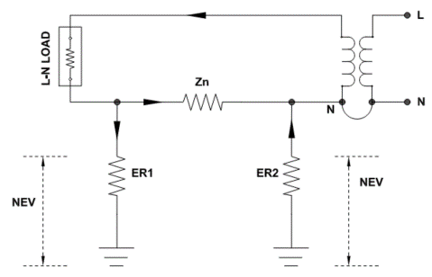
Flow of neutral return current through physical earth is the is the second mechanism of stay voltage generation.
Figure 7 shows stray ground current entering ground rod at an electrical service. Voltmeter is connected to ground rod and potential relative to ‘remote earth’ is measured.
Negative effects of stray voltage
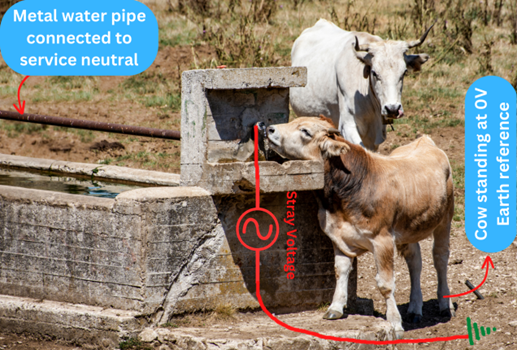
Though the mechanism of stray voltage due to neutral current flow can be understood by circuit theory, the way stray voltage affects comfort of humans or animals is not so obvious. Let’s look at figure 8. Neutral and ground are bonded at the customer’s electric utility service. The ground so derived is connected to all exposed metallic parts in the farm building such as metallic plumbing lines, electric milking machines, water stations etc. per local electric codes. NEV is thus ‘transferred’ to otherwise grounded (0V) objects.
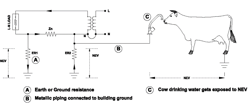
When an animal bridges the gap as shown, NEV potential is applied across the animal. Dairy cows are especially vulnerable as the distance between their mouth and hind legs is long. Cow’s mouth will be at NEV potential while the hind legs will be at ground (0V) potential causing current flow which can cause discomfort and pain. Dairy cows may respond to this by being agitated near certain locations, reduced milk output, develop mastitis etc.
A familiar location where NEV can be of discomfort to humans is swimming pools. By code metallic components in the pool, light fixtures, metallic handles etc. are grounded to service ground which in turn is connected to distribution circuit neutral. A person touching metallic handle and standing on water (assumed to be 0V) can get a slight tingling sensation or even shocked if NEV is high.
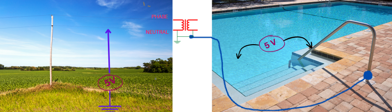
Figure 9 shows how NEV of 5V on the utility line gets transferred to swimming pool metallic handle due to primary to secondary neutral connection.
Terrifying video of kids shocked in pool
Read: Step and Touch Potential
Methods to mitigate Stray Voltage
Stray voltage due to NEV is a natural consequence of operating the power system and will always be present to some extent. When the NEV gets above 2V it is a good idea to take actions to rectify the condition. There are few things that can be done to minimize NEV and thus stray voltage. These are:
- Replace single phase distribution lines with three phase four wire lines with balanced load on each phase. When loads are perfectly balanced there won’t be neutral current and hence no NEV.
- Reduce the impedance of neutral return conductors by sizing the wires correctly and checking terminations for corrosions and loose connections.
- Reduce the earth resistance of individual pole grounds so that magnitude of NEV is minimized.
- Avoid use of multi grounded neutral system.
- Avoid use of bare concentric neutral cables.
Some additional methods to mitigate the effects of stray voltage [NEV] are:
- Create equipotential ground planes so that voltage gradient for humans and animals is eliminated. This is especially useful in farm buildings, swimming pools etc. NEC article 547.10 and 680.
- Neutral blocking device or MOV arrestor installed between primary and secondary neutral. Care should be taken to ensure other utility grounds (Telephone, CATV) do not bypass this device.
References:
D. W. Zipse, “Death by grounding,” 2008 55th IEEE Petroleum and Chemical Industry Technical Conference, Cincinnati, OH, USA, 2008, pp. 1-11, doi: 10.1109/PCICON.2008.4663964.
N. Abed, S. Salem and J. Burke, “Evaluation of induced stray voltages from transmission lines using EMTP,” IEEE PES General Meeting, Minneapolis, MN, USA, 2010, pp. 1-5, doi: 10.1109/PES.2010.5589404.
Public service commission of Wisconsin: Stray Voltage
EPRI; Identifying, Diagnosing, and Resolving Residential Shocking Incidents, TR-113566, Oct 05, 1999