Ghost or Phantom voltage is the voltage that is capacitively coupled from an energized conductor to a nearby conductor that is either open circuited at either ends or otherwise terminated in a very high impedance. Ghost or phantom voltage only appears in AC circuits.
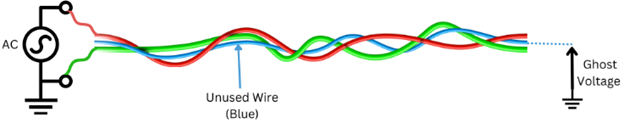
In electrical power wiring it is common to pull extra wires for future use. These circuits that are open circuited at either ends and installed in the same conduit as the energized conductors can indicate ghost voltage when measured between the conductor and ground using a modern digital multimeter. Ghost voltage can be few volts to almost as high as voltage on adjacent conductor. Due to small value of stray wire-wire capacitance typically associated with these installations, ghost voltage is a very weak source and cannot energize a circuit or otherwise cause shock hazard. Challenge while suspecting a ghost voltage condition is to reliably identify voltage as ‘ghost’ or ‘real’. By using a low impedance analog meter or dual impedance modern digital multimeter, ghost voltage can be identified.

Note: Terms ghost and phantom voltages are used interchangeably in the industry to describe the same phenomenon. In this article ghost voltage will be used to describe the phenomenon. Term stray voltage is sometimes used which adds to the confusion. Stray voltage is most commonly used to identify voltage generated between two objects due to normal power system current flow and not capacitively coupled voltage like ghost or phantom voltage. In this article term stray voltage is not used.
Link to: Common impedance coupling in power systems
Theory behind origin of ghost voltage
Consider a circuit shown in figure 2. Conductor C1 is energized from an AC voltage source. Conductor C2 is open circuited on both ends. Capacitance C12 is the capacitance between C1 and C2. C2G is the capacitance between conductor 2 and ground. Capacitance of C1 to ground is not relevant to the origin of ghost voltage.
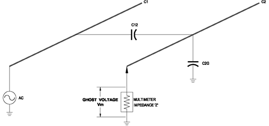
Voltage ‘Vm’ measured at C2 using a DMM (digital multimeter) with high input impedance Z, is given by:
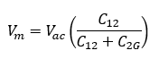
Voltage measured between C2 and ground is the result of capacitive voltage divider circuit comprised of C12 and C2G and is independent of frequency.
Link to: Capacitive impedance calculator
When meter input impedance is high (modern DMM), circuit C2 is not loaded [low burden], and the meter displays the voltage per the equation above. Typical DMM input impedance is between 5-10 Mega ohms (MΩ).
When the same circuit is measured with a low impedance (3-5 kΩ) DMM, circuit C2 is now loaded [high burden]. Capacitively coupled voltage is a very weak source and low impedance DMM will cause capacitive voltage to discharge through DMM. If voltage is ghost, the meter will display close to zero volt. If voltage is not ghost, then meter would display correct voltage.
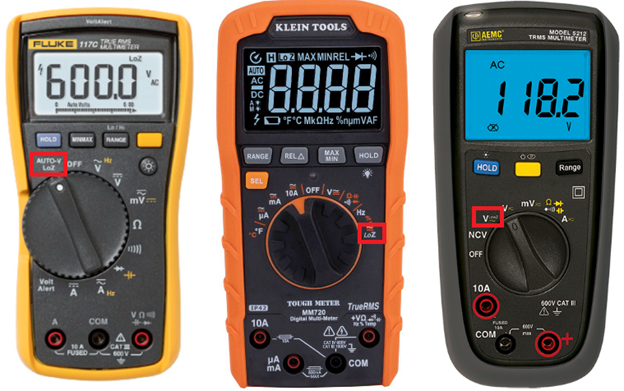
Figure 3 shows from left to right, Fluke 117, Klein MM720, AEMC 5212.
Many digital multimeter (DMM) manufacturers offer dual-impedance meter with selector switch to identify ghost voltage. Standard voltage measurement will be done using normal voltage selector which has high input impedance. If user suspects ghost voltage, then switch to low-Z (low impedance) option. Input impedance of two popular DMM for standard and low impedance voltage measurement is given below.
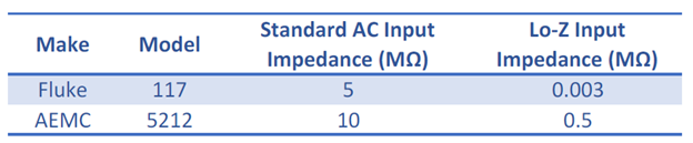

Fluke also manufactures an attachment called ‘SV225: stray voltage eliminator’ for use with any high-impedance digital multimeter (≥ 1MΩ) which accepts 4 mm safety shrouded banana plugs. When this adapter is used with digital multimeter (DMM), internal 3kΩ load is presented to the circuit under measurement which will dissipate any capacitively coupled energy on the wires.
This is a useful adapter to use with DMM that do not have lo-Z feature. Working principle of this adapter is similar to lo-Z DMM, in that both lo-Z DMM and Fluke SV225 offers low impedance to the measured circuit.
Link to: Power quality check using multimeter
Why aren’t all digital multimeters low impedance?
If the application is to measure power system voltage (<600V) then all measurements can be reliably carried out with low-impedance (lo-Z) digital multimeter (DMM) which also has the added benefit of detecting ghost voltage.
When measurements need to be done with weak source such as extra low voltage [ELV] circuit, 24VAC circuit, serial communication etc., a low-impedance DMM will ‘load’ the circuit and hence affect the accuracy of voltage reading or otherwise affect the performance of circuit under test.
- If your work is primarily in electronics, standard DMM with high input impedance will be sufficient.
- If your work only involves measuring power system voltages (<600V) then a high impedance standard DMM will suffice.
- If your work involves testing and troubleshooting building wiring and controls with long wires, then DMM with dual impedance capability will be very useful.
Link to: Open neutral condition and stray voltage
How does Ghost voltage look like?
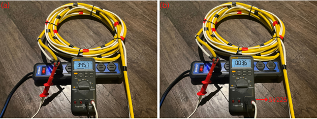
Test circuit was made to view ghost voltage on a multimeter and on an oscilloscope to identify if wave shape looks anything like a ghost. In this experiment, coaxial cable that is open circuited on both ends is taped to an extension cord energized with 120VAC. Open end voltage of loose coax is then measured using a standard DMM which indicates 34.57 V.
When the same circuit is measured with a lo-Z meter (using SV225 attachment) meter displays close to zero volts which confirms this is ghost voltage. Any other meter with lo-Z option would have indicated the same.
Ghost voltage is then captured on an oscilloscope which is shown in figure 5.
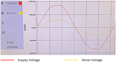
As seen from figure 5, ghost voltage is not scary. Ghost voltage waveform has same frequency and follows the same wave shape trajectory as source voltage but has lesser in magnitude.
Link to: Voltage unbalance
Conclusion Ghost voltage or Phantom voltage is the term used to describe capacitively coupled voltage on unused open circuited or otherwise high impedance terminated load. Ghost voltage is a weak source and is not capable or energizing or creating shock hazard. Use of modern digital multimeter (DMM) with high impedance is the main reason that ghost voltage is measured. Identifying voltage as ghost or real is a challenge that can be easily accomplished by using a low-impedance digital multimeter. Manufactures of DMM offer dual-impedance DMM to address this phenomenon. Ghost voltage waveform looks similar to the source voltage with same frequency but has lower magnitude. Ghost voltage can be detected by one of the following methods:
- Insert load by means of a resistor. If voltage is ghost, DMM will display zero volts.
- Insert load by means of a test lamp. If voltage is ghost, test lamp will not glow.
- Use dual impedance digital multimeter. Switch to lo-Z mode to confirm ghost voltage.
- Use stray voltage eliminator such as Fluke SV225.