POWER FACTOR BASICS
Power factor for an AC circuit operating with sinusoidal waveform is defined as the cosine angle between voltage and current phasors.
Complex apparent power S (volt-ampere) can be defined as:

A pure resistor will only absorb real power (watts). Ideal capacitor delivers reactive power and ideal inductor absorbs reactive power. Real and reactive power absorbed or delivered by RLC components are listed below. A positive value indicates power is absorbed while a negative value indicates reactive power is delivered.

From equations above, resistor only absorbs real power, inductor absorbs zero real power and absorbs reactive power. Capacitor absorbs zero real power and delivers reactive power.
Link to Power Factor Calculator
Inductive loads (motors, reactors etc.) will cause reactive power to flow from electric utility through service transformer to the load. Reactive power (Kvar) that is drawn is in addition to useful power (KW) that the load is demanding.
Transformers are rated in terms of KVA. The combination of kVAR and kW flowing through the transformer will use up the available transformer KVA per the equation below:

Release of Transformer Capacity
Active power that can be delivered by a transformer is a function of power factor (PF) of the load. Higher the PF (closer to 1.0), larger the active power that can be supplied by transformer. Lower PF causes transmission of reactive power through the transformer which causes additional active power loss and voltage drop in the transformer. A higher tap may have to be chosen by adjusting the transformer tap changer in this case. In general, operating a transformer with low PF could result in:
- Overloaded transformer
- Higher operating temperature
- Higher voltage drop
- Higher losses
Link to: Transformer current calculator
If power factor of load is improved by adding capacitor bank at the load or at the secondary side of transformer, transformer is able to carry additional load (kW). If the system had an existing overload, PF improvement can eliminate it. If there was no overload, improving PF can release transformer capacity and postpone adding expensive new transformers and switchgear to serve additional loads. Release of transformer capacity can be looked at two ways:
- Constant transformer kVA: Improving PF will increase kW capability
- Constant load kW: Improving PF will release transformer kVA capacity
Constant transformer kVA: Available apparent available power (kVA) of transformer can be considered constant except when one of the transformer cooling methods is used.
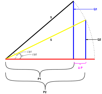
Referring to figure 1, at power factor angle 𝞍1, reactive power demanded by load is Q1. Notice that the corresponding active power (kW) that can be delivered by the transformer (without overloading) is P1. When load power factor is improved to a lower angle of 𝞍2, the corresponding reactive power is Q2. Notice that corresponding to Q2, the active power that can be delivered is now P2 which is an improvement of ΔP. This is the mechanism by which PF improvement helps with additional transformer loading.
Since transformer apparent (S) power kVA is constant:

Based on equation above, lets consider an example with original PF1 of 0.5 and improved PF2 of 1.0. Then the ratio of PF1/PF2 is 0.5 which means new power P2 can be double the previous power P1.
Read: How to calculate reactive power of transformer?
Constant load kW: When real power (kW) demand P is constant, improving PF by supplying capacitive kVAR will help ‘release’ of transformer kVA capacity. This extra capacity can be used to feed new loads. In figure 2, real power P (kW) is constant. By supplying reactive kVAR, PF angle is reduced from 𝞍1 to 𝞍2. This results in a net reduction of kVA demand ΔS.
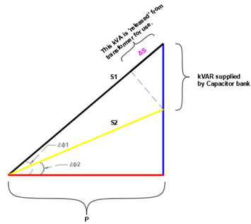
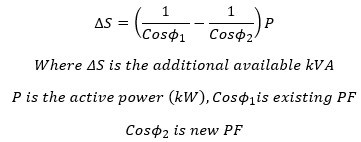
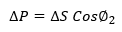
Additional kW load ΔP that can be added corresponding to the ‘released’ load ΔS can be calculated as:
Where to add PF correction: Primary or Secondary of Transformer?
Adding PF correction at the primary of transformer do not help with release of transformer capacity. Central PF correction at primary will improve overall PF at primary connection to electric utility and can help with PF surcharges. However, reactive power still has to flow through the transformer and no extra advantage is gained. Instead, by applying PF correction at secondary side or at the load, transformer is relieved from carrying reactive kVAR and hence improvement of capacity is obtained.
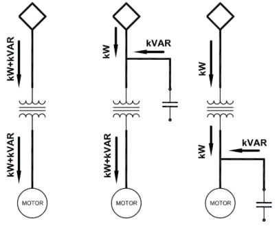
Adding correction at the load (motor etc.) is the recommended method. Current and kVA in the branch circuit and service transformer is reduced and makes an efficient system.
Often time it is not feasible for correction at individual loads and applying central correction at secondary of service transformer is an attractive choice for many users. While this method does not relieve branch circuits from carrying reactive current, it does relieve the service transformer from carrying those reactive vars. See figure 3.
Read: Star and delta connection of capacitors
When relief of an overloaded transformer is desired, the amount of kVar that need to be added depends on the amount of capacity that need to be released. In some instances, correction to unity may be economical compared to cost of installing a new transformer.
Read: Overcompensation of reactive power for induction motors