When excessive amounts of reactive power compensation (PF Correction) is applied to terminals of induction motor, it can result in self excitation and over voltage condition during motor switch off. The recommended practice is to size the capacitor to around 80% of the reactive power demand at no load condition. Overcompensation of motors is often is not intentional and usually happens when motors are relocated to a new starter location or when swapping motors with different magnetizing characteristics.

If the power factor correction capacitor is sized higher than the recommended value, then there a possibility that the motor magnetizing inductance and the power factor capacitors form a resonant circuit as the motor is switched off and is slowing down. A motor that is switched off has stored magnetic energy in its air gap which collapses as time progresses. Collapsing magnetic field results in current in the rotor which in turn induces a voltage on the stator. This voltage will initially be close to system frequency (50/60Hz) and will decay over time as the rotor speed dies down.
Any combination of inductor and capacitor has a resonant frequency. If the motor capacitor is oversized, then there is a possibility that this resonant frequency is below the system frequency (50/60Hz). As the motor slows down, induced voltage frequency dies down from system frequency and as it passes though the resonant frequency of the capacitor-motor inductance combination, a resonant condition can be set up. Resonance can cause overvoltage condition at the terminals of the motors and can lead to insulation failure or flashover at the motor or at the capacitor.
Link to series and parallel resonance in power systems
Solution to this problem is to have the capacitor-motor resonant frequency always above the system frequency (50/60Hz). One way to guarantee that is to size the capacitor to around 80% of the motor reactive power demand at no load condition. The resonant frequency of such combination will be always higher than the system frequency and there will not a situation when the motor decaying terminal voltage frequency matches the resonant frequency.
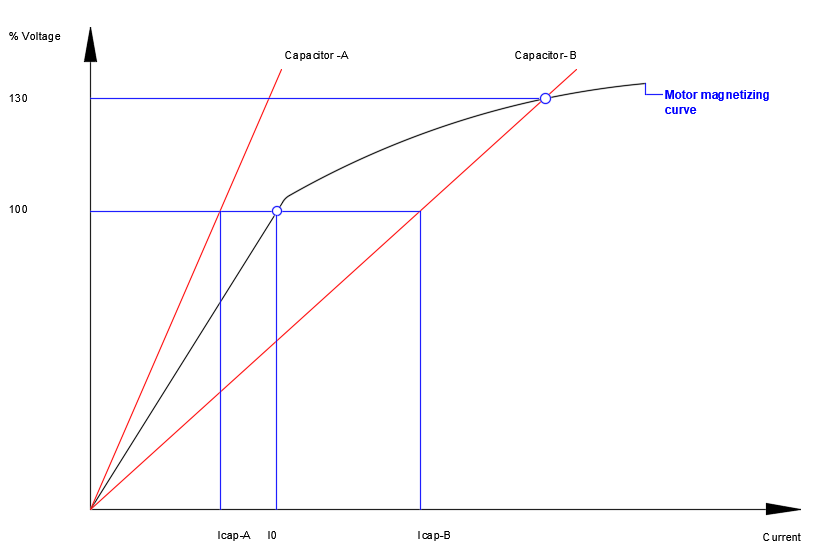
Referring to the graph below, Capacitor-A is sized to less than 80% of the reactive power demand of the motor. The capacitor-A graph will never intersect the motor magnetizing curve and there will not be any adverse effects. On the other hand, Capacitor-B is sized higher than the reactive power demand of the motor. The capacitor-B current is greater than the motor magnetizing current. It can also be observed that a stable operating point (at 130% voltage in this example) is possible with the higher capacitor bank size. This operating point can occur when the motor is switched off and the motor speed is slowing down. This point will result in higher voltage across the motor and capacitor and could result in insulation damage.
It is possible to estimate the resonant frequency of the motor-capacitor circuit. The capacitance will be the equivalent wye capacitance of the capacitor bank connected to the motor. Relevant equations are shown below.
Medium voltage (>1000V) capacitors can be connected in delta or wye. It is common to find delta connected capacitors for typical motor power factor applications.
Link to kVar to uF conversion
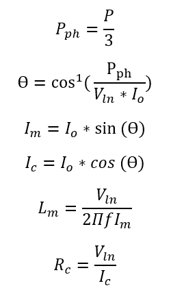
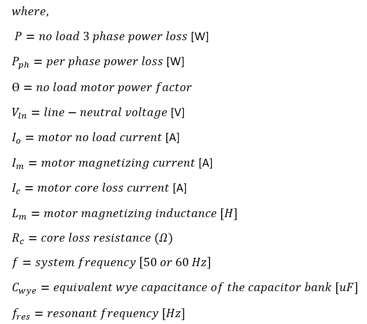
Motor magnetizing inductance is usually not available. Instead for large motors the manufacturer provides the no load power loss and the no load current. From these two values the motor magnetizing reactance/inductance can be approximately calculated. These values can also be obtained by running motor on no load and measuring the no load current and no-load power. The relevant equations are shown below.
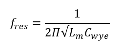
Once the equivalent wye capacitance of power factor capacitor and motor magnetizing inductance is calculated, the motor-capacitor self-resonant frequency can be calculated using:
If the calculated self-resonant frequency is above the system frequency [50/60Hz] then there is no problem. If the self-resonant frequency is below the system frequency, then there is a problem and the capacitor size need to be reduced.
Note: Power factor capacitors can have anywhere from 0-15% of tolerance from the published value. Use the high tolerance when calculating.
The easiest way to mitigate the problem of self-excitation is to use the manufacture recommended capacitor bank size.
Application Considerations
Use motor manufacturer recommended capacitor bank size.
Two motors even with the same horse power (HP) can have different magnetizing impedance and hence different maximum size of capacitor bank that can be connected. This is due to the differences in the magnetic circuit of motors.
If capacitor sizing is performed based on field measurements, then size the capacitor to compensate 80% of the reactive power demand of the motor at no load.
The self-resonant over voltage condition can persist for longer duration if the motor has high inertia and takes longer to stop. Longer stop time keeps the motor speed at the resonant value and hence cause more stress to the winding.
The damage to the motor may not be immediate and may happen over an extended time frame as the insulation gets stressed over time.