Basics of single-phase motor starting: A single phase motor connected to a single-phase supply will not rotate as the windings do not produce rotating magnetic field. For one half cycle of the AC waveform torque will be produced in one direction and then in the opposite direction for the next half cycle thereby cancelling out rotor torque. The motor can however be manually turned, and it will continue rotate in the direction it was turned. This is not a reliable way to start motor. To make the motor start, a rotating magnetic field must be set up. There are few different ways to realize single phase motor connection that results in rotating magnetic field. They are:
* Capacitor Start Motor
* Permanent Split Capacitor Motor
* Capacitor Start Capacitor Run Motor
* Split Phase Motor
Capacitor Start Motor
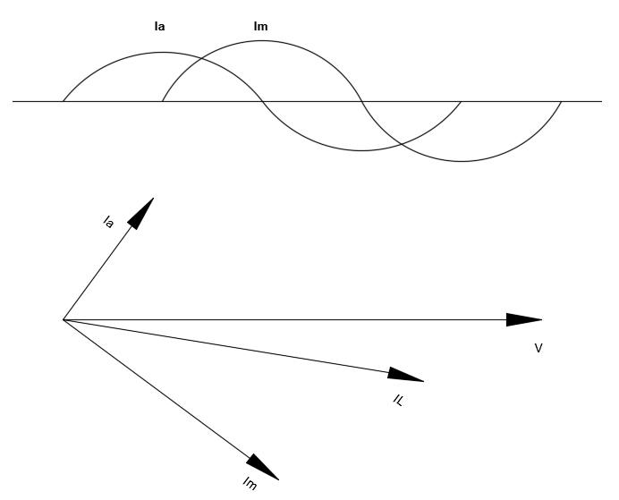
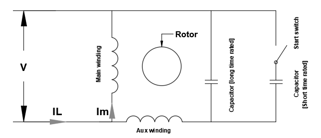
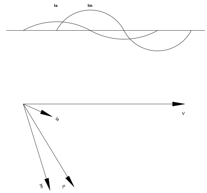
Capacitor start motors are single phase induction motors that have two winding- Main winding and Start winding in which the start winding has a series connected capacitor. The current following through the start winding (with capacitor) will have 90-degree phase angle difference (ideally) compared to the current flowing through the main winding. Due to this phase angle difference, a resultant rotating stator magnetic field is produced which will rotate the rotor. Single phase motor diagram using capacitor start is shown below.
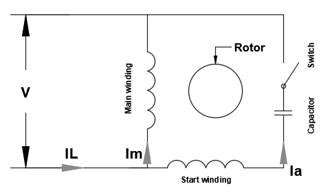
Once the motor starts and a desired speed is reached, a rotor mounted centrifugal switch will open the switch thereby disconnecting the capacitor from the circuit. This arrangement permits the use of short time rated capacitor and hence lower the cost of the motor.
Capacitor start motors are used for hard starting loads such as compressors, conveyers, pumps and some machine tools.
Permanent Split Capacitor Motors
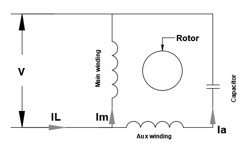
Permanent split capacitor (PSC) motors have two windings called main winding and auxiliary winding. A capacitor is connected permanently in series with the auxiliary winding. The main winding and auxiliary winding are electrically mounted 90 degrees apart. In addition, due to the presence of capacitor, the current flowing through the auxiliary winding will lead the current in the main winding (current in capacitor leads the voltage). Due to this a net rotating magnetic field is set up in the stator which makes the rotor rotate.
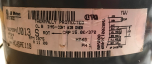
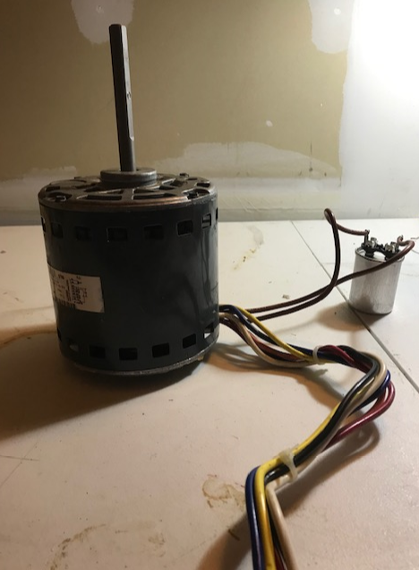
A permanent split capacitor motor name plate is shown above. In this case the manufacturer recommends 15 uF of capacitor with voltage rating of 370VAC.
The selection of capacitor is a compromise between cost, starting torque and running characteristics. PSC motors are quiet and have high efficiency. PSC motors are used in fans, blowers in heating and air conditioning applications.
Capacitor Start Capacitor Run Motor
Balanced two phase operation of motor at starting and at other speed can be achieved by connecting two capacitors in parallel at starting- resulting in a capacitor start capacitor run motor. On starting both capacitors will be in circuit and once the speed reaches close to about 80% the start capacitor opens and only the run capacitor will be in circuit. Starting capacitor will be a large electrolytic capacitor and the run capacitor is usually of oil filled paper type/ low loss polymer and of lesser value. The large starting capacitor gives the motor a larger starting torque and the run capacitor is used to improve running characteristics.
Two value capacitor motors are quiet, smooth running and have higher efficiency.
Split Phase Motor
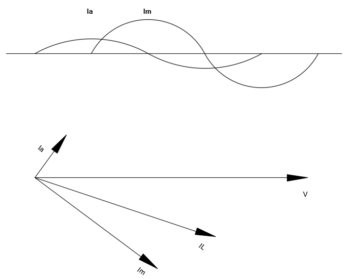
Split phase induction motor has two windings- main winding and start winding. Start winding uses smaller (thinner) wires that has higher resistance and has lesser turns (lower inductance and lower X/R ratio) than the main winding. This results in start winding current to be more in phase with the applied voltage compared to the main winding. This phase angle difference which is not the ideal 90 degree but more around 30 degrees or less is sufficient to create a small rotating magnetic field and start the motor. The torque for such motors will be low due to this less than ideal phase angle difference between the winding currents.
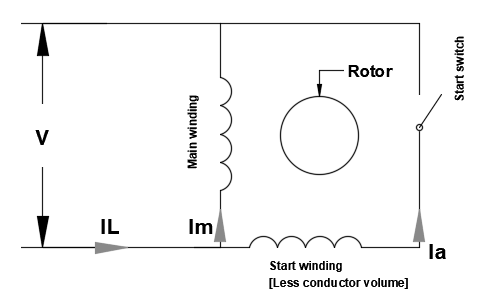
Once the motor starts a rotor mounted centrifugal switch disconnects the start winding and the motor continues to run on the main winding. The starting current for such motor tends to be higher than capacitor start motors while the running characteristics are as good as other types of single-phase motor starters.
Split phase induction motors are used to start easy to start loads such as fans, saws etc.
Additional Reading: Motor Calculator, Motor Starting Current Calculator