Autotransformer starting of motors is used widely in starting large industrial motors due to its advantage of providing the highest starting torque with lowest starting line current compared to other reduced voltage starting methods. These are also known as ‘korndorfer’ starter. The problems with starting large motors across the line are many – some of which are excessive voltage sag and tripping of sensitive equipment etc. Practically, if across the line starting of motor creates a voltage sag (dip) of more than 80% then other methods of starting needs to be investigated. One of the most economical and robust reduced voltage starting method is autotransformer based starting and is most commonly used in medium voltage motor starters.
Link to Motor starting calculator , Motor current calculator
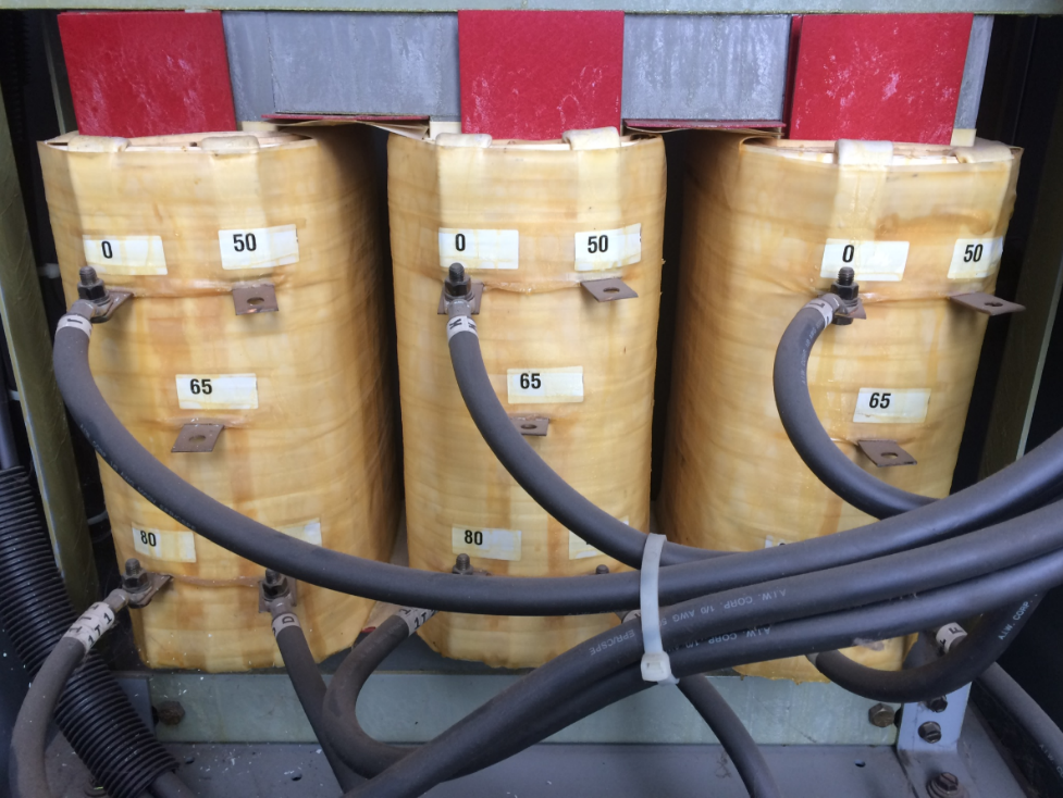
Autotransformer starting involves inserting an autotransformer in between the motor and the source. The voltage that is fed to the autotransformer input is reduced in proportion to the ‘tap’ setting of autotransformer at the output. Typical settings for tap settings for autotransformer motor starters are 50%, 65%, 80%.
As an example, for an autotransformer tap setting of 50%, the following will be true:
1 Motor starting current: Motor starting current will be reduced in proportion to the tap setting. A tap setting of 50 % will deliver 50 % less motor starting current compare with regular full voltage starting.
2 Line current: Line current varies as the square of the applied voltage. A 50% tap will reduce line current by 25% compared to full voltage starting. Line current determines the system voltage sag (or dip) during a motor start. A reduction of starting line current will help in reducing motor start voltage sag magnitude.
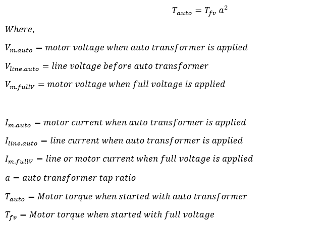
3 Motor Torque: Motor torque varies as the square of the applied voltage. For a 50% tap setting the torque will only be 25% compared to the full voltage starting.
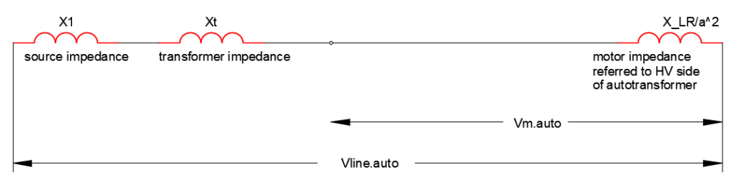
Consider a three-phase wye connected autotransformer based motor starter as shown in the figure below.
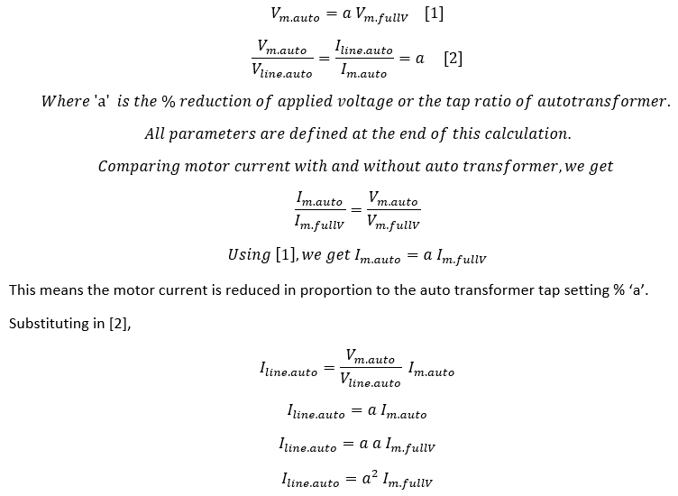
Line current with auto transformer is reduced quadratically in proportion to the tap setting of auto transformer. A 50% tap will reduce line current by 25%.
Starting torque with auto transformer varies quadratically in proportion to applied voltage. A 50% tap (hence 50% less voltage) will reduce motor torque by 25%.
Autotransformer starting current calculation
************************************************************************************************************************************************
Operation of a practical autotransformer starter
Schematic of an auto transformer starter is shown below. There are three main contactors that play critical role in auto transformer reduced voltage starting. They are the start contactor ‘S’, main contactor ‘M’ and the run contactor ‘R’. Readers are encouraged to identify these in the figure below.
See that the start contactor ‘S’ connects all three phases of the system together to create a neutral point. This ‘neutral’ will be internal to the starter and will be at zero voltage potential. This point should not be grounded.
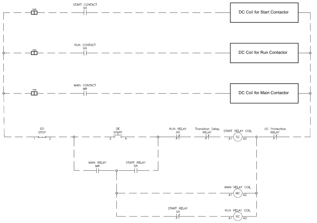
The start sequence of the autotransformer starter is as follows:
When the start button is initially pressed, the start relay coil ‘SC’ gets energized through the path shown.
This in turn closes the normally open start relay contact ‘SR’ and energizes main relay coil ‘MC’ which in turn closes the contact ‘MR’.
On the power circuit, this sequence results in closing of the start contactor ‘S’ and main contactor ‘M’ and the motor is connected to the power source and starts accelerating. For the tap settings shown in figure above (65%) only 65% of the supply voltage is applied across motor windings. With the reduced voltage applied across windings, the motor begins to accelerate and gain speed. With the reduced voltage, a fully loaded motor will stop accelerating after some time. At this instant (which has to be either calculated or set based on trial and error or listening to motor noise) the ‘transition delay relay’ will open there by deenergizing the ‘start relay coil’ which opens contact ‘SR’. This transition delay can be obtained in multiple ways:
1 Perform motor starting analysis
2 By observing the motor high pitch starting noise and timing when the motor stops accelerating
3 If the motor relay has autotransformer start functions available, then use one of the following:
*Current base transition (most preferred): In this type of transition control, the transition delay relay will only open once the motor current has fallen below a certain set value (usually around 125% of motor FLA). A separate incomplete sequence timer needs to be programmed in the relay and if the motor current does not fall below the set current level in the specified time, the relay should initiate trip of motor circuit breaker.
*Current and time-based transition: In this type of transition control, the transition delay relay will only open once the motor current has fallen below a certain set value (usually around 125% of motor FLA) and a separate timer has expired.
*Time based transition (least preferred): In this type of transition control, transition delay relay will open once the set timer has timed out irrespective of the motor current. The drawback with this scheme is that even if the motor is jammed or otherwise fails to accelerate, or the timer is set incorrectly, the START contactor will open, and the RUN contactor will close. With a jammed motor, the START contactor will have to interrupt the highly inductive locked rotor current of the motor which has been the cause of many autotransformer failures.
Once the ‘start relay coil’ is deenergized, the autotransformer acts as a series reactor until the time the run contactor is closed. This means the motor is always connected to the supply and there is no temporary disconnection from the source (like star-delta starter). Do to the fact that motor is always connected to source there won’t be any large current or torque pulsation when transition happens.
Deenergizing the start relay coil will power up the run relay contact ‘RC’ which closes the ‘RUN’ contactor. The autotransformer is now not part of the circuit and motor gets full voltage across its windings and will accelerate to its synchronous speed. This is the start sequence for most commercial auto transformer starters designs.
For stopping the motor, release the ‘Stop’ push button in the drawing above which will unlatch all the relays thereby opening the ‘Main’ and ‘Run’ contactor.
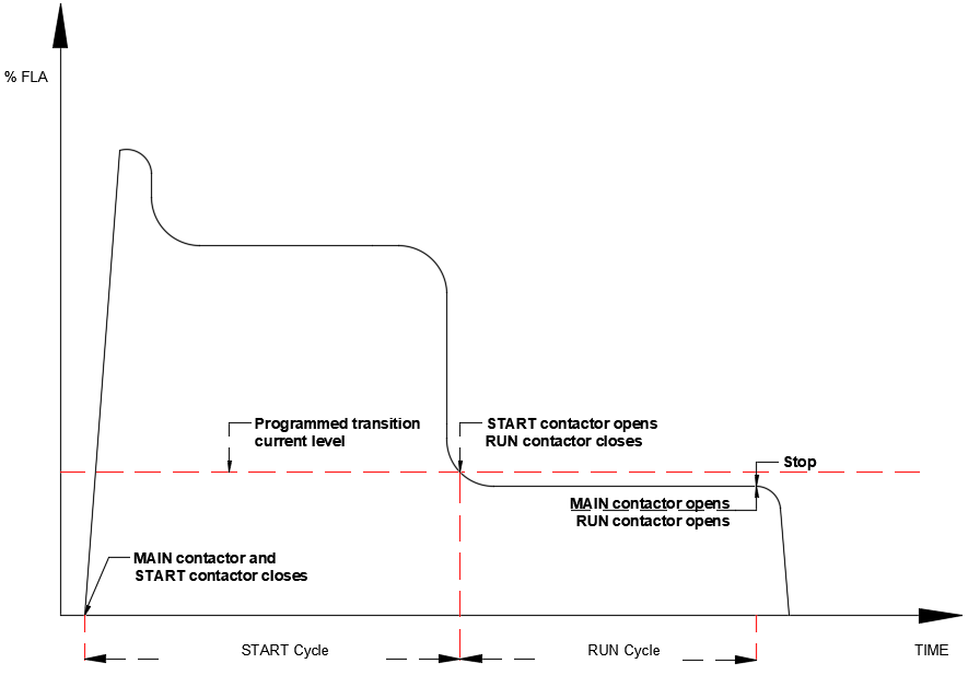
Typical autotransformer starting current follows the pattern below.
Other Considerations
1 When motor is wye connected, the autotransformer is preferred to be wye connected and if the motor is delta connected then the auto transformer is preferred to be connected in delta.
2 Two single phase auto transformers can be used instead of three phase wye connected connection. This is acceptable from starting performance perspective. However, when two single phase auto transformers are used, during starting the terminal voltages will be temporarily unbalanced. This can cause increased heating while the motor is accelerating.
3 Many failures of autotransformer tap-tap voltage flash overs are reported. Some design considerations to mitigate these incidents are:
a) Use three coil-three leg autotransformers instead of the older practice of using two coil- three legged designs.
b) Use current as the basis of transition and not just time. Once the current drops to below the set value (usually 125%), transition can occur. If the current does not drop below the set value after a set delay the starter should be set to trip on fault. Transition on current and time (current + time) is also acceptable.
4 Consider autotransformer heat rise (along with motor heat rise) when deciding on maximum allowable starts per hour. Just like motor, autotransformer too gets heated rapidly during motor start phase. If sufficient cooling time is not provided between starts the windings can fail due to overheat.
5 Incorporate surge arrestors in to the auto transformer starter.
6 Incorporate motor surge protection to protect motor from damaging transients due to vacuum contactor switching in the starter.
Additional Reading:
Motor Differential Protection, Motor Current Calculator, Motor Starting Current Calculator