Differential protection of induction motors provides very sensitive protection against internal phase -phase and internal phase-ground faults. Motor needs to have six winding leads brought outside to install either one set of three phase CT or two sets of three phase CT depending on the design. One set of motor leads are brought out on the line side (U1, V1, W1) and the other set is brought out on the neutral side (U2, V2, W2). Differential protection relay (87m) provides the fastest and most reliable protection against internal faults and is often used as the first line of defense. Standard overcurrent protection relay settings have to be set above the locked rotor starting current to avoid nuisance tripping during motor start. This leaves the motor vulnerable to internal short circuits. This is where differential protection excels because the relay can be set very sensitively to capture low level faults in the motor.
Commonly, differential protection is used for large (>2000HP) medium voltage motors or large motors that are very critical or expensive.
There are three styles of motor differential protection.
1 Core Balance Type
2 Current Summing Type
3 Biased Differential Type
1 Core Balance: In this method, two wires from the same phase are routed through the same CT which is usually located inside the motor termination box. The CT is then wired to a protective relay that has instantaneous function (50). This relay when activated can either directly trip the motor or send a signal to the motor relay to trip the circuit breaker feeding the motor.
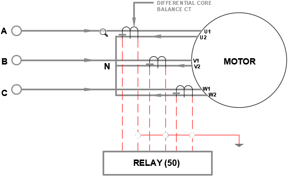
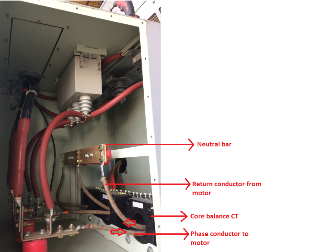
Below is picture of motor differential relay using core balance method. Phase conductors (black) enter from the top and passes through the 50:5 core balance CT and land on motor terminals (U1, V1, W1) inside. Conductors from motor neutral side (U2, V2, W2) is wired through the same 50:5 CT and is terminated on a neutral bar. Other components seen in the termination box are for motor surge protection.
Advantages of Core balance method:
*Under normal running conditions, the net current/flux in the CT will be zero. This means a low ratio CT can be used for differential relay applications. Commonly a 50:5 CT is used even for large medium voltage motors. Only when the window size offered by a 50:5 CT does not permit routing of cables through it a larger 100:5 CT may be considered.
*This method is less prone for false differential currents that can arise due to CT asymmetry or asymmetrical starting currents.
*Generally, this method is more economical than other methods and occupies less physical space.
*Any relay which has instantaneous over current function can be used with this scheme. This is due to the fact that only one set of three phase CT leads need to be terminated on the relay. The relay will need to actuate only when current above a certain limit is detected for above a certain preprogrammed time.
Disadvantages of Core balance method:
*If the motor cables are large such that two cables cannot be passed through the small CT (50:5 or 100:5), then this method is not practical. If this is the case, consider one of the other methods listed below.
2 Current Summing: In this method six CTs are required. One set of CT is for the phase leads on one side of the motor and the next set covers the phase leads on the neutral side of the motor as shown in the figure below.

Advantages of Current summing method:
*If the motor cables are large and cannot be routed through the small ratio CT for core balance scheme, then this method is an attractive option.
*Any relay which has instantaneous over current function can be used with this scheme.
Disadvantages of Current summing method:
*Since each CT will see the full motor current, CTs need to match the load current rating of the motor. Due to this reason, the CTs will be larger and bulkier than core balance method.
*Since exact matching of CT on either side motor winding may not be possible, asymmetrical starting current can create false differential currents. To over come this the sensitivity of the differential system may have to be sacrificed.
*Another source of asymmetry that can occur is due to different CT secondary lead lengths for CT on the line side of motor and on the neutral side of the motor. The lengths should be made approximately same to avoid unbalanced CT performance during a fault or motor start up.
*In general, this method occupies more physical space and involves more field wiring.
*Require six CTs.
3 Biased Differential: In this method six CTs are required. One set of CT is for the phase leads on one side of the motor and the next set covers the phase leads on the neutral side of the motor as shown in the figure below. The main difference between this and the current summing method is that different ratio CTs can be used on the opposite sides of the motor (if needed). The CT ratio mismatch can then be compensated in the differential relay.

Advantages of Biased differential method:
*Allows different ratio CTs to be used.
*Modern electronic differential relays allows compensating for nonstandard CT polarity connections.
*Since traditional differential relays are used, this scheme permits the use of highly sensitive yet robust dual slope characteristics of differential relay. This prevents misoperation during external faults, CT saturation during motor starting etc.
Disadvantages of Core balance method:
*Since each CT will see the full motor current, CTs need to match the load current rating of the motor. Due to this reason, the CT will larger and bulkier than core balance method.
*In general, this method occupies more physical space and involves more field wiring.
*Scheme requires a traditional differential relay (87) that accepts 6 current inputs.
*Requires six CTs.
Why motor neutral should not be grounded?
With large motors with six leads (U1, V1, W1) and (U2, V2, W2) a common question is whether the star point of the motor can be earthed/grounded. The start or neutral point of the motor is not recommended to be grounded because:
*Grounding the neutral provides a path for external ground fault currents to flow through the motor winding.
*Any circulating zero sequence ground currents in the system will now have a path back to source through the neutral of the motor. This leads to additional and unnecessary heating of motor winding.
*From a protection perspective, grounding of motor neutral provides no additional benefit plus it causes lot of harmful effects as listed above.
Read: Transformer Differential Protection, Medium Voltage Cable Shield Grounding